
CB-Series Panel Replacement Instructions
In the event of a necessary solar panel replacement on a CB-150, CB-250, or CB-450 solar tower due to prolonged submersion, corrosion, UV exposure, or physical damage, follow the process below. For older models, the entire panel set will require replacement to install a new, easily accessible junction that allows for individual panel replacement, if necessary, in the future.
Warning: Cover each panel fully during this process to avoid any current flowing throughout the panel assembly.
Old Panel & Junction Removal
- Use a 9/16″ wrench or socket to remove the (6) outer screws connecting the tower to the buoy.
- Once removed, invert the solar tower to view the internal solar panel junctions. Ensure to remove all top-side mounts or sensors before inverting.
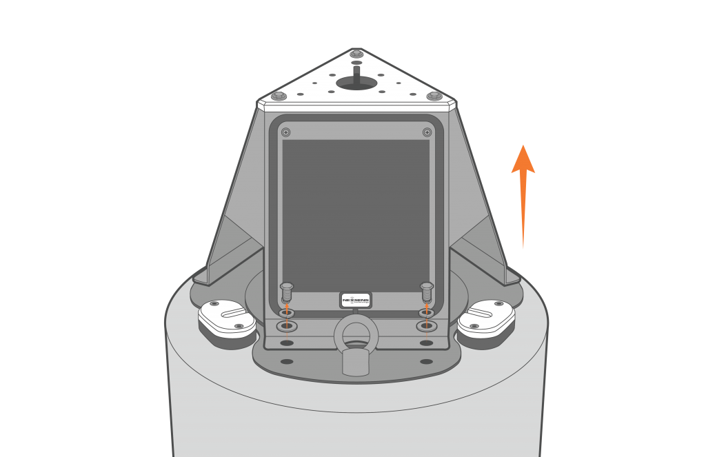
Figure 1: Remove the solar tower.
- Use a Philips screwdriver and 3/8″ wrench or socket to remove the (4) screws holding down each solar tower.
- Ensure to keep these screws, unless entirely corroded, as these will be used to install the new solar panels.
- Replacement nylon nuts (10-32 Nylon Insert Hex Locknuts, 316SS) may be necessary as these nuts may seize, or the nylon may have become less effective over time.
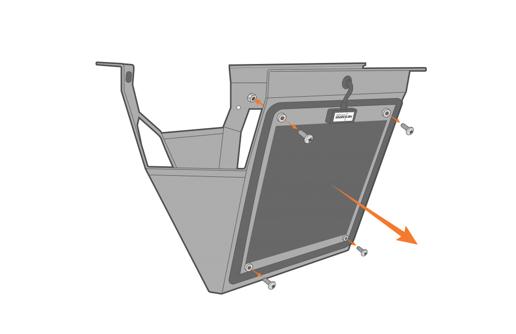
Figure 2: Remove the screws on the solar tower.
- Once all the panels are loose, cut the cable going from each solar panel junction to its corresponding internal junction.
- Cover the panel or lay it flat on the panel face to avoid substantial amounts of current flowing through the panels while performing this step.
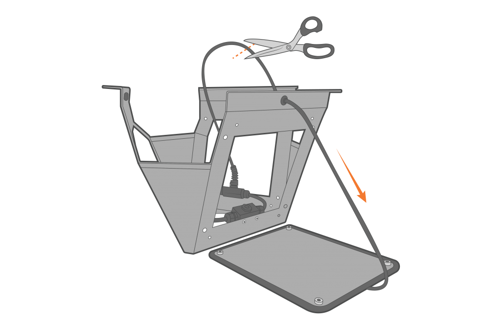
Figure 3: Cut the junction wire cable.
- Use a Philips screwdriver to remove the (2) set screws holding each internal junction to the solar tower.
- Remove the entire internal junction assembly. Cables on the junction assembly will be routed through various cable clamps mounted within the solar tower. These may be kept to conveniently route the new solar panel cables.
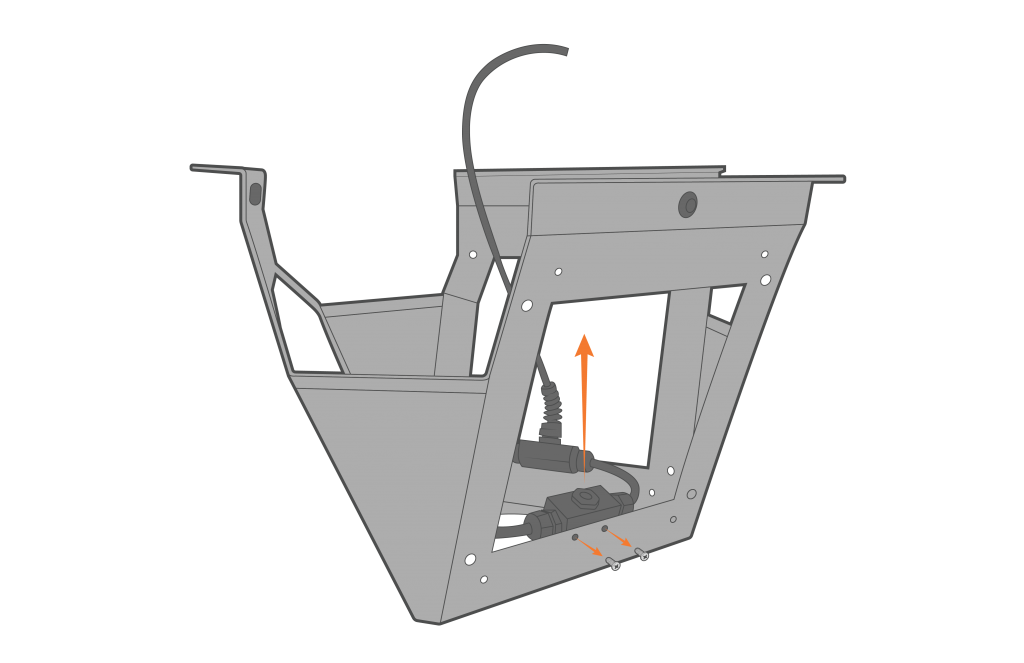
Figure 4: Old solar panel junction removal.
New Panel & Junction Installation
- On any of the (3) available spots previously held by the internal junctions, use (2) set screws to install the new solar panel junction.
- Ensure the (3) 2-pin connectors are pointing up (down when the tower is on the buoy) to allow for panel connection.
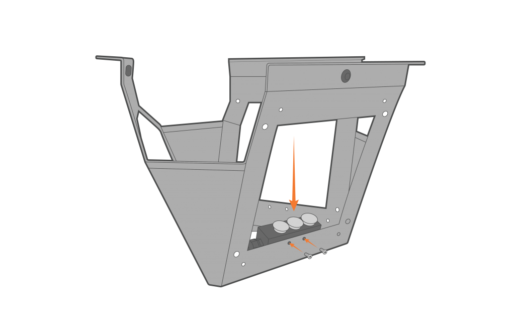
Figure 5: Install the new junction.
- Install the new panels onto each side of the solar tower.
- The cable on the backside of the panels should be pointing down (up when the tower is on the buoy).

Figure 6: Install the new solar panels.
- Connect the 2-pin plug connectors into the 2-pin receptacle ports on the new internal panel junction.
- Ensure an O-ring is on all of the connectors before connecting.
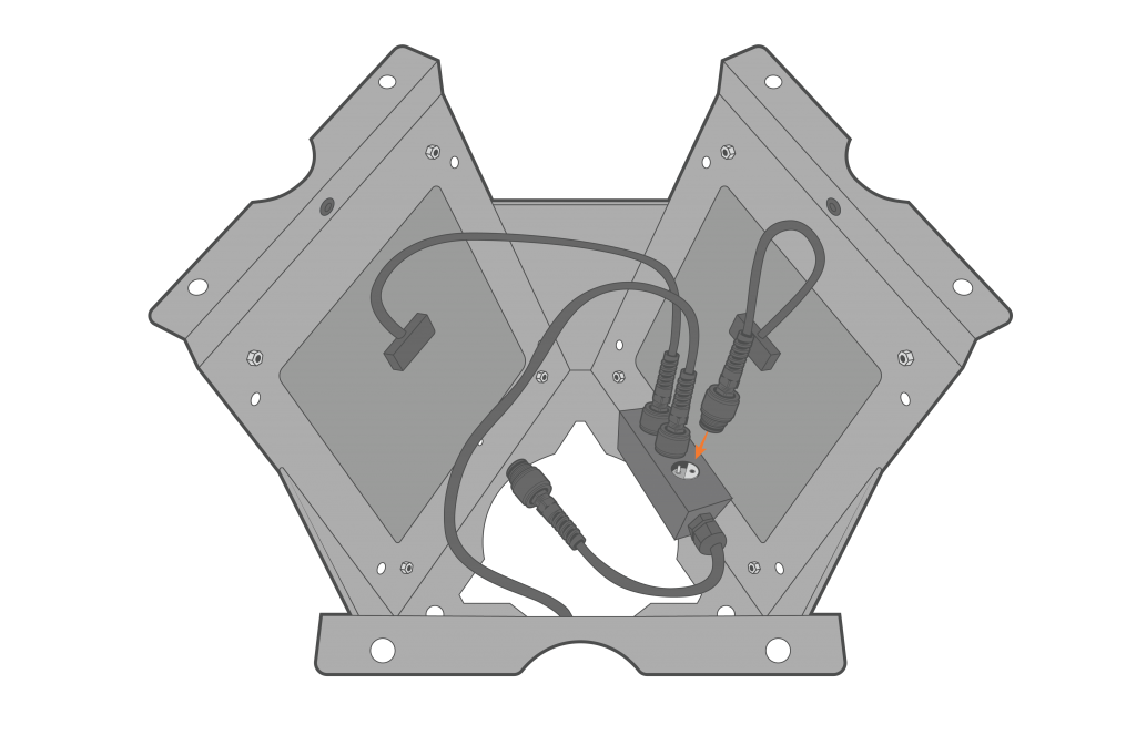
Figure 7: Plug in the solar panels.
Future Panel Replacement
If necessary in the future, individual panels may be replaced by disconnecting the panel of concern from the internal junction and installing a new panel provided by NexSens. It is recommended to complete this process in a controlled environment such as an office or laboratory, and to test the overall conditions of the panel assembly by following the article below: