Connect 4-20mA Sensor to mV-485 Adapter
- Wiring the sensor. A 56 Ohm resistor is required to convert mA to mV.
- Configure the mV-485 Adapter. Connect using iChart (see Connecting to a mV-485 Adapter).
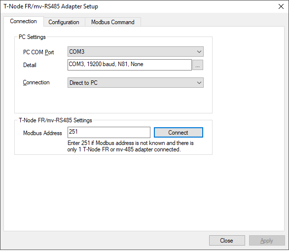
Connect via iChart.
- Set 4-20mA scaling. In the Edit Sensor field of the Configuration menu, select Generic from the drop down list. Use 224 mV and 1120 mV for scaling:
Point 1: mV1 = 224; Value1 = <value corresponding to 4 mA>
Point 2: mV2 = 1120; Value2 = <value corresponding to 20 mA>
The screenshot below shows an example of a 4-20 mA temperature sensor with 4mA = 0C and 20mA = 50C.
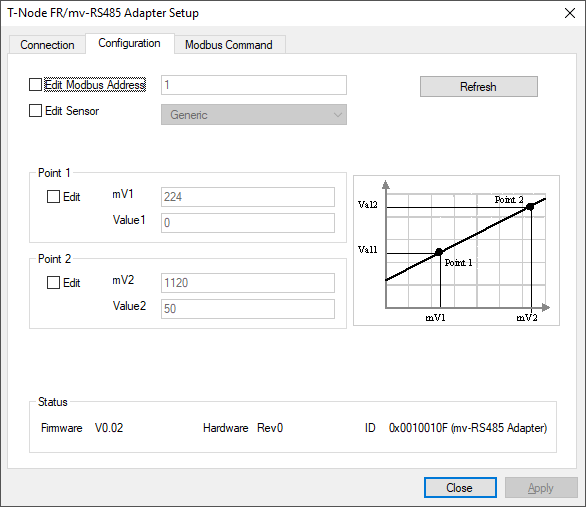
Example configuration of 4-20 mA sensor.
- Test the connection. Most 4-20 mA transmitters have a test function where the output is locked to 4mA and 20mA or set to an arbitrary mA value for testing.
- Lock the sensor output to 4 mA, read mV (Reg: 0x0002). It should read around 224 mV.
- Lock the sensor output to 20 mA, read mV (Reg: 0x0002). It should read around 1220 mV.
- Set the sensor output to an arbitrary mA output, read mV, divide the mV by 56 to convert to mA. Verify this is what the sensor output is set to.

Read test values to confirm configuration.
- Convert mV to sensor reading. Use the following equation to convert from mV to measurement units:

Where:
- mV is from the Read mV function from step 4
- mV1, Value1 are Point 1 scale from step 3
- mV2, Value2 are Point 2 scale from step 3
Example:
- Use the temperature sensor example in step 3. If the mV reading is 672 mV:

Connecting mV-RS485 adapter to NexSens UW-FWP
The receptacle end of the mV-RS485 adapter may be connected to the plug end of the NexSens UW-Field Wireable Plug (UW-FWP). Below are the pinouts of the mV-RS485 adapter and UW-FWP, along with the signals that are passed through to the J terminals on the UW-FWP.
Note: For 4-20 mA sensors, a 56-ohm resistor must be jumped between mV+ and mV-.
| mV-RS485 receptacle pin number | UW-FWP plug pin number | UW-FWP | Actual Signal | |
| Terminal Name | J-Pin | |||
| 1 | 8 | RS-485 A | J8 | mV+ |
| 2 | 7 | RS-485 B | J7 | mV-* |
| 3 | 6 | SDI-12 | J6 | — |
| 4 | 5 | 12V | J5 | 12V |
| 5 | 4 | 5V | J4 | — |
| 6 | 3 | RS-232 Rx | J3 | — |
| 7 | 2 | Ground | J2 | Ground* |
| 8 | 1 | RS-232 Tx | J1 | — |
*In some applications (i.e., using a loop powered 4-20 mA sensor), a common ground must be established between all ground sources including mV- and ground on the UW-FWP.
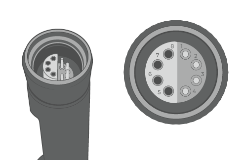 mV-RS485 adapter receptacle pinout. |
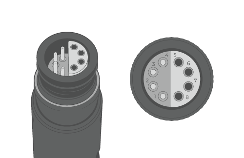 UW-FWP plug pinout. | 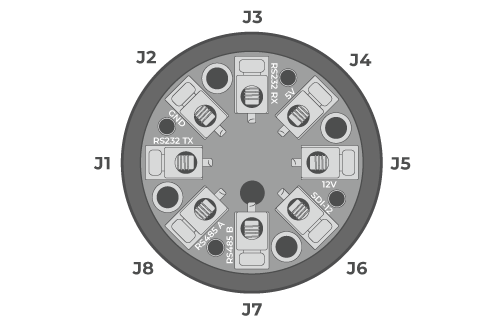 UW-FWP terminal pinout. |
