
Connecting to a mV-485 Adapter
NexSens mV-485 adapters can be used to connect sensors with voltage outputs (e.g. 0-5 VDC) to the iSIC, SDL 500 or X2 data loggers when an analog port is not available. The adapter reads the mV output from the sensor and converts it to RS-485 Modbus format. Each adapter must be configured for the specific sensor to which it is connected. This internal configuration is performed through iChart software. In order to set the configuration, a connection must be established to the adapter using the following process:
*Skip to the Connection through an iSIC data logger section if not using a UW-USB-485R cable to connect directly to a PC.
Direct Connection to a PC
- Connect the plug end of the mV-485 adapter with the receptacle end of a UW-USB-485R cable.
- In iChart, go to Advanced | TNode FR/mV-RS485 Adapter.
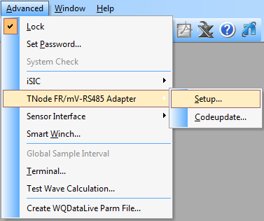
Open configuration menu.
- Enter the appropriate communication settings and Modbus address of the adapter to be configured. Select the following:
- Connection type: Direct to PC
- Correct PC COM Port. If a COM port is unknown, click here for instructions to identify it.
*If the Modbus address is unknown, the universal address 251 can be used to find the device, but only if it is the only Modbus device connected. Otherwise, the exact address must be entered in the Modbus Address field.
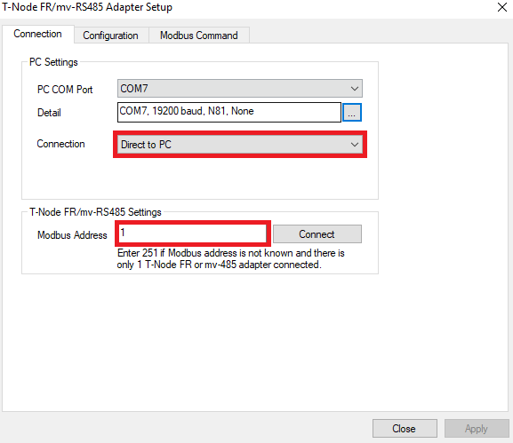
Direct to PC communication settings.
- Click the Connect button to open a connection to the device. When the button changes to Disconnect, click the Configuration tab to access the configuration settings. If the current configuration of the device does not show correctly, go back to the Connection tab, check the settings, and retry the connection.
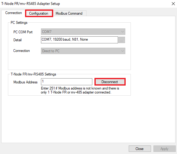
Access Configuration menu.
*Skip to the Adapter Configuration section once connected directly to the PC.
Connection through an iSIC data logger
- Connect the plug end of the mV-485 adapter with the receptacle port or digital terminal of an iSIC or SDL500 data logger.
- In iChart, go to Advanced | TNode FR/mV-RS485 Adapter.
Open configuration menu.
- Enter the appropriate communication settings and Modbus address of the adapter to be configured. Select the following:
- Connection type: Through iSIC
- iSIC Address
- Correct PC COM port. If a COM port is unknown, click here for instructions to identify it.
*If the Modbus address is unknown, the universal address 251 can be used to find the device, but only if it is the only Modbus device connected. Otherwise, the exact address must be entered in the Modbus Address field.
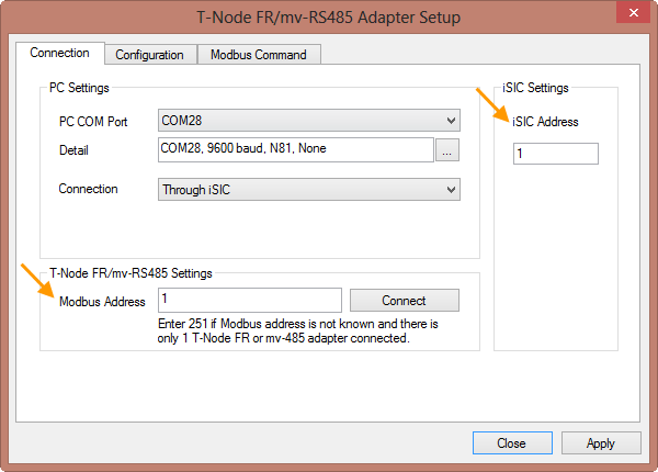
Through iSIC communication settings.
- Click the Connect button to open a connection to the device. When the button changes to Disconnect, click the Configuration tab to access the configuration settings. If the current configuration of the device does not show correctly, go back to the Connection tab, check the settings, and retry the connection.

Access Configuration menu.
Adapter Configuration
- Verify that the adapter configuration has been read successfully. The Modbus address, sensor type and scaling factors should all display.

Confirm connection.
- Once connected, the menu can be used to:
- Select the type of sensor to be used with the adapter and set the scaling factors
- Change the Modbus address of the adapter
- Change the gain setting of the adapter
- Set a zero offset
- If any settings are changed, click Apply to submit the changes.
- When finished, go back to the Connection tab. Click Disconnect to terminate the connection. Then, click Close to exit the menu.