
NX260 Turbidity Sensor User Guide
The NexSens NX260 Turbidity Sensor is an optical, self-cleaning sensor designed to measure turbidity. It is ideal for construction sites, dredging projects, stormwater monitoring, and other water quality applications where suspended sediments and water clarity are a concern.
1. Install software and set up the computer
- Download and install NexSens CONNECT software on a field or lab computer.
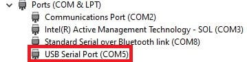
- Plug the MCIL-6-FS to USB cable adapter into the computer.
- Ensure the computer has access to the internet so the USB VCP drivers install automatically.
- Open Windows Device Manager and note the COM port for the USB Serial Port.
- If the device does not install properly, contact your IT administrator to manually install drivers from the VCP Driver download.
2. Power the sensor and prepare for measurements
- Connect the sensor to the cable.
- Plug the DC power adapter into a wall outlet. The wiper will activate on power up (three back and forth cycles).
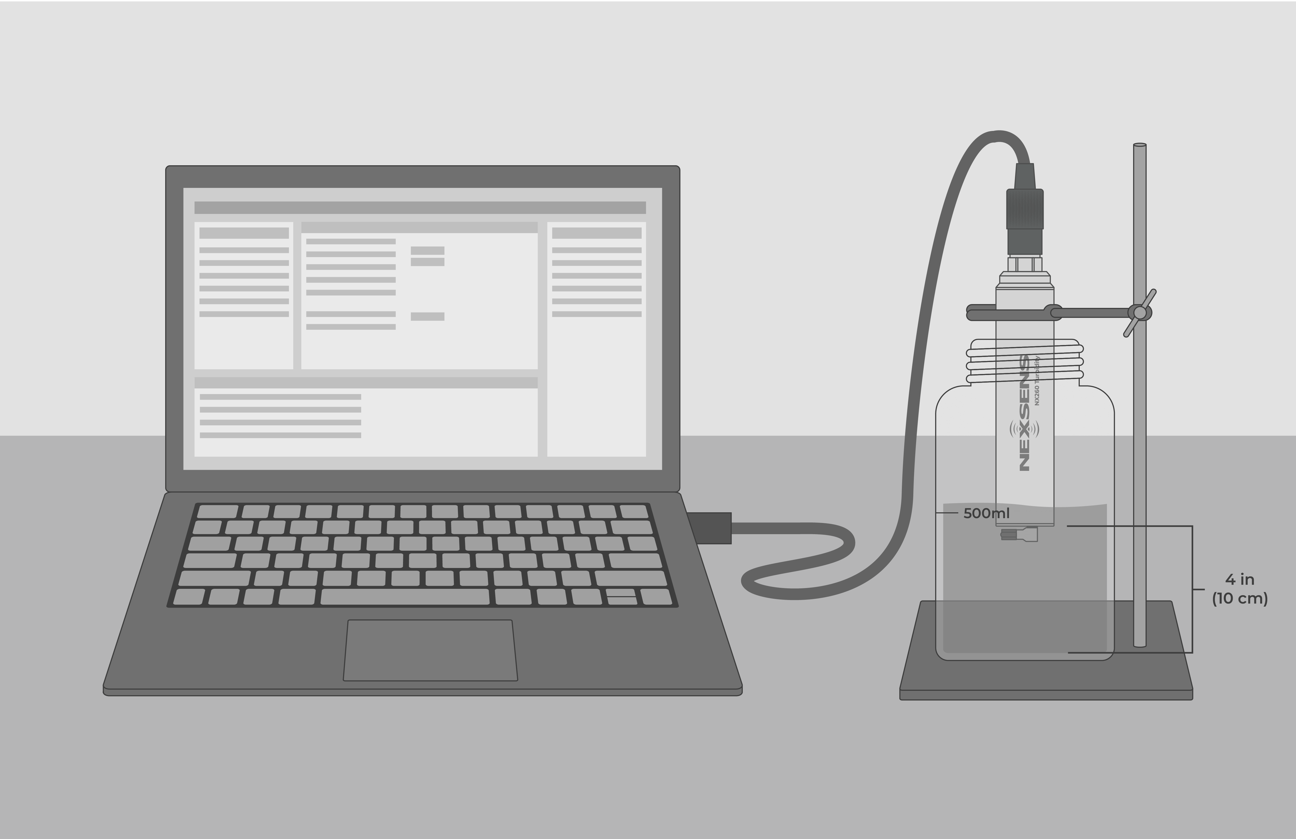
- Half fill a 1-liter amber-colored bottle with clean tap water.
- Suspend the sensor in the center, a minimum of 4 inches (10 cm) from the bottom. This will reduce reflected and ambient light interference.
3. Confirm sensor connection and function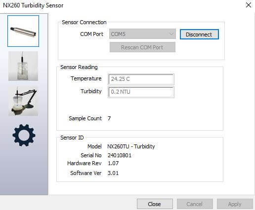
- Open CONNECT software and go to Tool → Sensor → NexSens NX260 Turbidity
- Select and Apply the previously noted COM port, and sensor readings will begin updating.
- Click the gear icon to activate the wiper.
- When the wiper finishes the cleaning cycle, note the tap water reading.
- If available, transfer the sensor to other samples with varying turbidity and watch the sensor readings. Always activate the wiper when entering a new sample to ensure the face is clean and free of bubbles.
- Rinse and dry the sensor before returning to the amber bottle to confirm the initial reading.
4. Calibrate the sensor
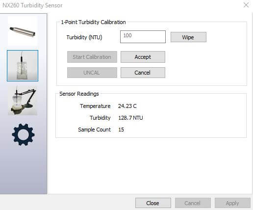 The NX260 supports one and two-point calibration. For most surface water applications, a two-point in 0 FNU and 100-200 FNU is recommended. The most recent calibration coefficients are stored within the sensor. Calibrations are performed one point at a time, and coefficients are updated individually. Follow Good Laboratory Practices (GLP) to ensure accurate readings. For best results, a stabilized Formazin standard, such as Hach Stablcal is recommended
- One-Point Turbidity Calibration
- Open the 1-Point Turbidity Calibration in the software
- Pour 500 mL of calibration reagent into an amber bottle.
- Suspend the sensor in the center and a minimum of 4 inches from the bottom.
- Enter the reagent value and activate the wiper.
- Click Start Calibration and allow 30 to 60 seconds for readings to stabilize.
- Once stable, select Accept.
- Rinse and dry the sensor.
- Two-Point Turbidity Calibration
 Go to Tool → Sensor → NexSens NX260 Turbidity in CONNECT software and open 2-Point Turbidity Calibration.
- Pour ½-liter into an amber bottle with the lower value reagent.
- Suspend the sensor in the center and a minimum of 4 inches from the bottom.
- Enter both reagent values (e.g., 0 and 100 FNU) and activate the wiper.
- Click Start Calibration and wait 30–60 seconds for readings to stabilize.
- Click Accept to store the first point.
- Rinse and dry the sensor.
- Place the sensor in the second reagent, wipe and allow 30–60 seconds for readings to stabilize.
- Click Accept to store the second point.
5. Post-Calibration Checks
- Return the sensor to calibration reagents and check that the sensor readings are within an acceptable tolerance.
6. Data Logger Connection
The NX260 interfaces to data loggers with RS-485 Modbus protocol or SDI-12 with an optional adapter.
Connecting to NexSens X-Series Data Loggers
- Use CONNECT Software to set the Modbus address.
- Go to Tool → Sensor → NexSens NX260 Turbidity in CONNECT software and select the Gear icon.
- At the top, enter the new Modbus address and select Update Sensor.
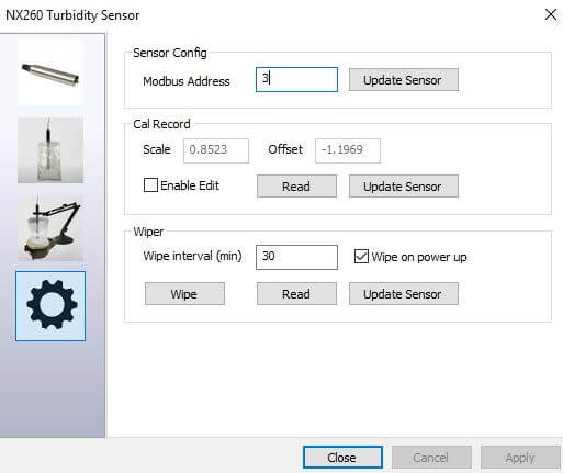
- Connect the sensor using the supplied cable to one of the open sensor ports on the logger and note the port number.
- Plug the X3 into the USB port of the computer and power it on with the AC power cable.
- Open CONNECT and select the SENSOR tab.
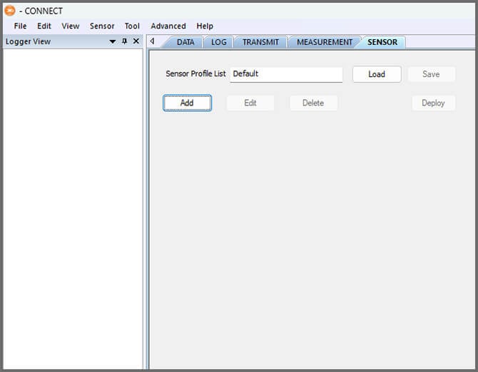
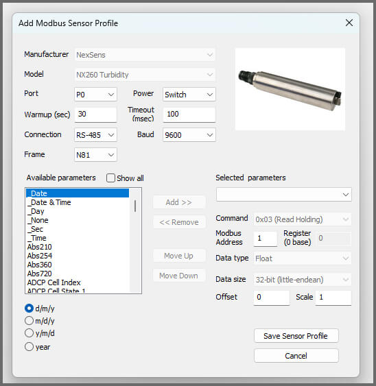
- Click Add and select NexSens from the Manufacturer drop-down. Then select the NX260.
- Set the port number.
- Select either Continuous or Switch in the Power drop-down.
- Switch power is recommended for the NX260 turbidity sensor.
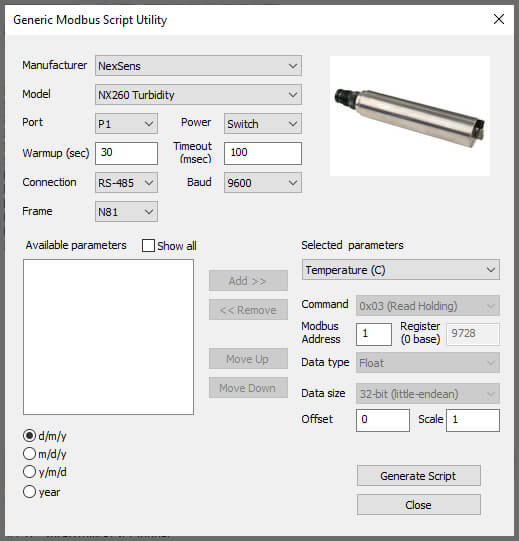
- Switch power is recommended for the NX260 turbidity sensor.
- Click Save Sensor Profile.
- Complete the setup for all other sensors, and then click Deploy.
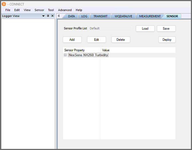

- Confirm that data is being transferred to WQData LIVE.
Connecting to SDI-12 Data Loggers
Use the optional RS485-SDI12 adaptor to convert the sensor to SDI-12. Connect as shown and follow standard SDI-12 protocol.
| Signal | Color |
|---|---|
| 12V | Red |
| Ground | Black |
| SDI | Brown |
| A | N/C |
| B | N/C |
Connecting to Other RS-485 Modbus Data Loggers
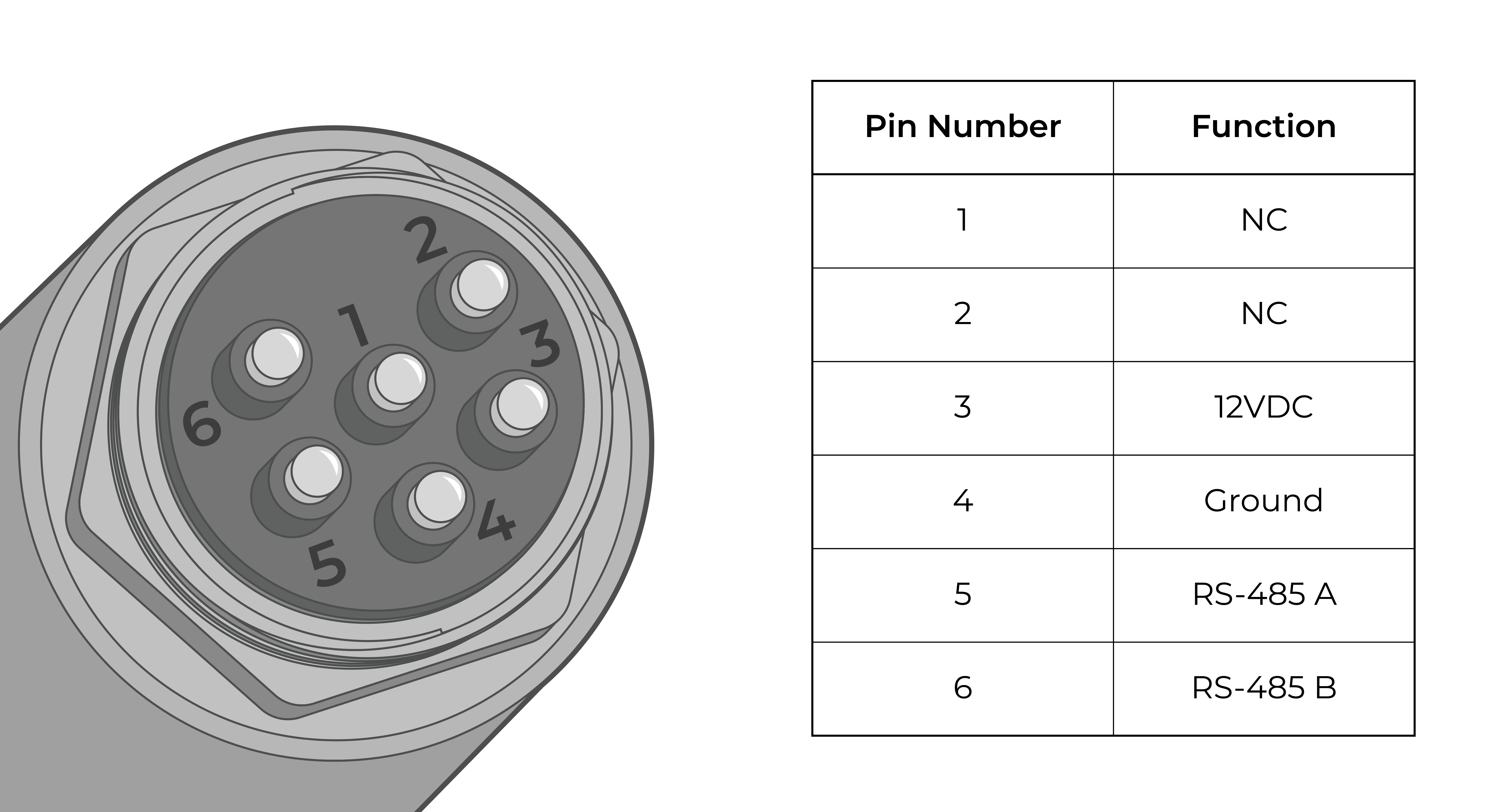
For other RS-485 Modbus data loggers, use the wiring pinout and Modbus commands found in Appendix A.
7. Mounting
Deployment setups will vary based on the platform, application, and site location. For general buoy mounting instructions and pole-mount assembly, see below.
Buoy-Based Deployments
First, follow the appropriate User Guide in the Knowledge Base for buoy assembly. There are two options for near-surface measurements and a third option for water column measurements:
Cage Mount
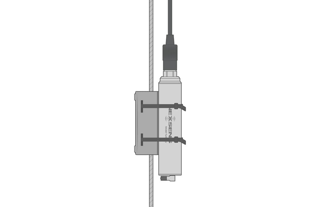
Use the NexSens Small Instrument Cage Mount to attach the sensor to the buoy cage.
- Strap the sensor to the gage leg with the mount and cable ties (as shown). The mount is supplied with a rubber adhesive liner to prevent the sensor from sliding.
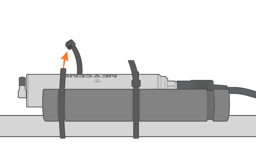

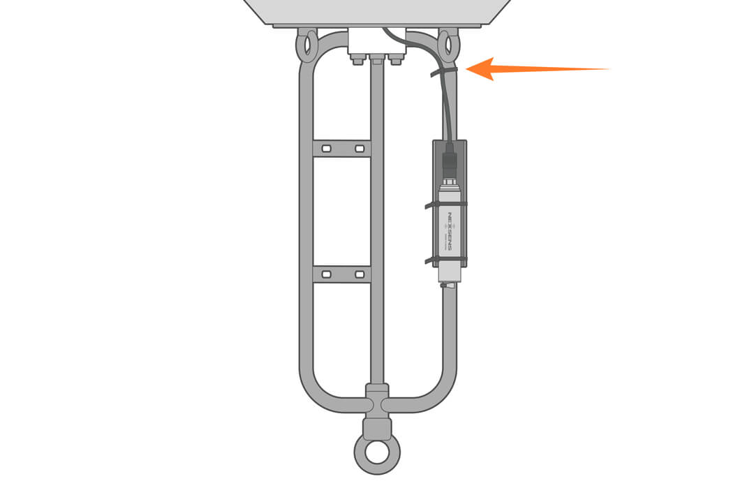
- Further secure the assembly by adding a few additional ties to the cable.
Buoy Deployment Pipe
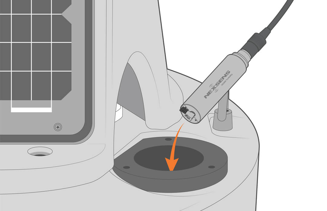
Optional perforated deployment pipes can be fitted to most NexSens CB– and XB-series buoys. Deploying the sensor inside the pipe provides easy access for maintenance and recalibration.
Water Column
Use the NexSens Instrument Mooring Clamp to securely attach NX260 to a sensor mooring line at the desired depth in the water column.
Shore-based Deployments
For dock, pier, or bank deployments, it’s best to secure the sensor in a perforated PVC pipe. Extend the pipe into the water and deploy the sensor.

8. Inspection and Maintenance
Periodic inspection and maintenance ensure that the NX260 provides reliable and accurate field measurements for long-term continuous operation. Follow a quality assurance plan (QAP) and agency requirements.
- Visit the monitoring site and perform a calibration check by leaving the sensor in place and making a nearby independent turbidity measurement with a field sampling instrument. The readings may be used as a QC data point to help understand sensor drift or used to determine calibration frequency.
- Pull the sensor from the water, and if fouled, clean it with tap water and a soft cloth. In extreme fouling environments, a brush and detergent may be needed. Be careful not to scratch the optical window, and do not turn the wiper by hand as this could damage the motor or gearbox.
- Calibrate the sensor if needed or required by the QAP.
- Check that the connection remains tight and return the sensor to the water.
- Before leaving the site, confirm data is again streaming to the cloud or base station.
Cleaning
Periodic cleaning will extend the life of the sensor and help ensure long-term quality data. Soak the sensor in a mild dish detergent for 10 to 15 minutes. Being careful not to scratch the optical sensing elements, lightly brush or wipe away any debris. If hardness and other deposits persist, soak the probe in a 50% by volume vinegar and water solution and brush or wipe as needed. Rinse and dry the sensor.
Wiper Replacement
Anytime the sensor is calibrated or cleaned, Users should check the wiper to ensure that there are no frays on the brush and that there are no black streaks on the sensor face. If either of these is noticed, the wiper should be replaced.
All NX260 sensors come with one Replacement Wiper Kit. Additional kits can be ordered online under part number: 260-wiper.
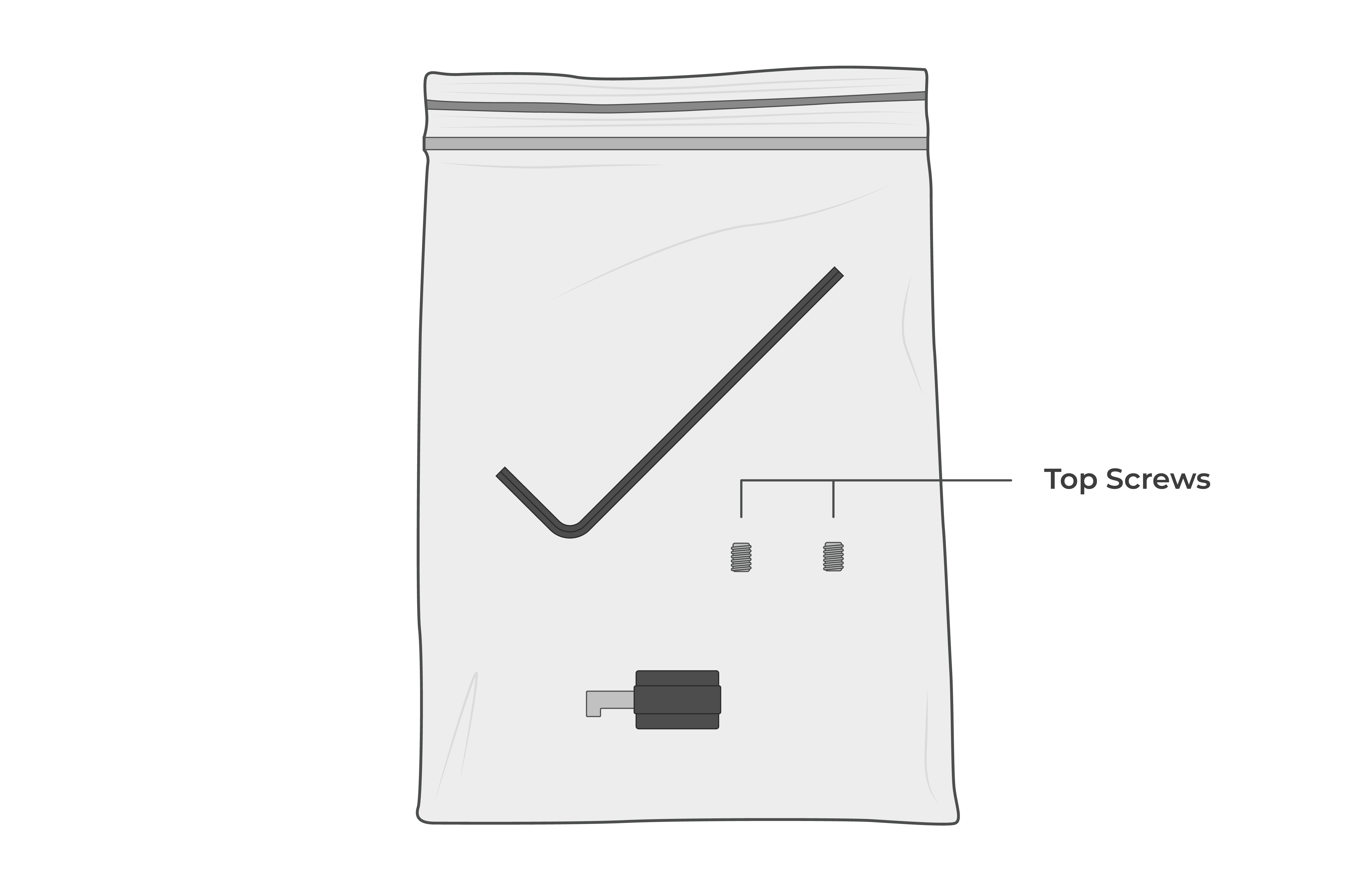
- Clean off the sensor and unplug it from the power source to stop the wiper from running during the replacement.
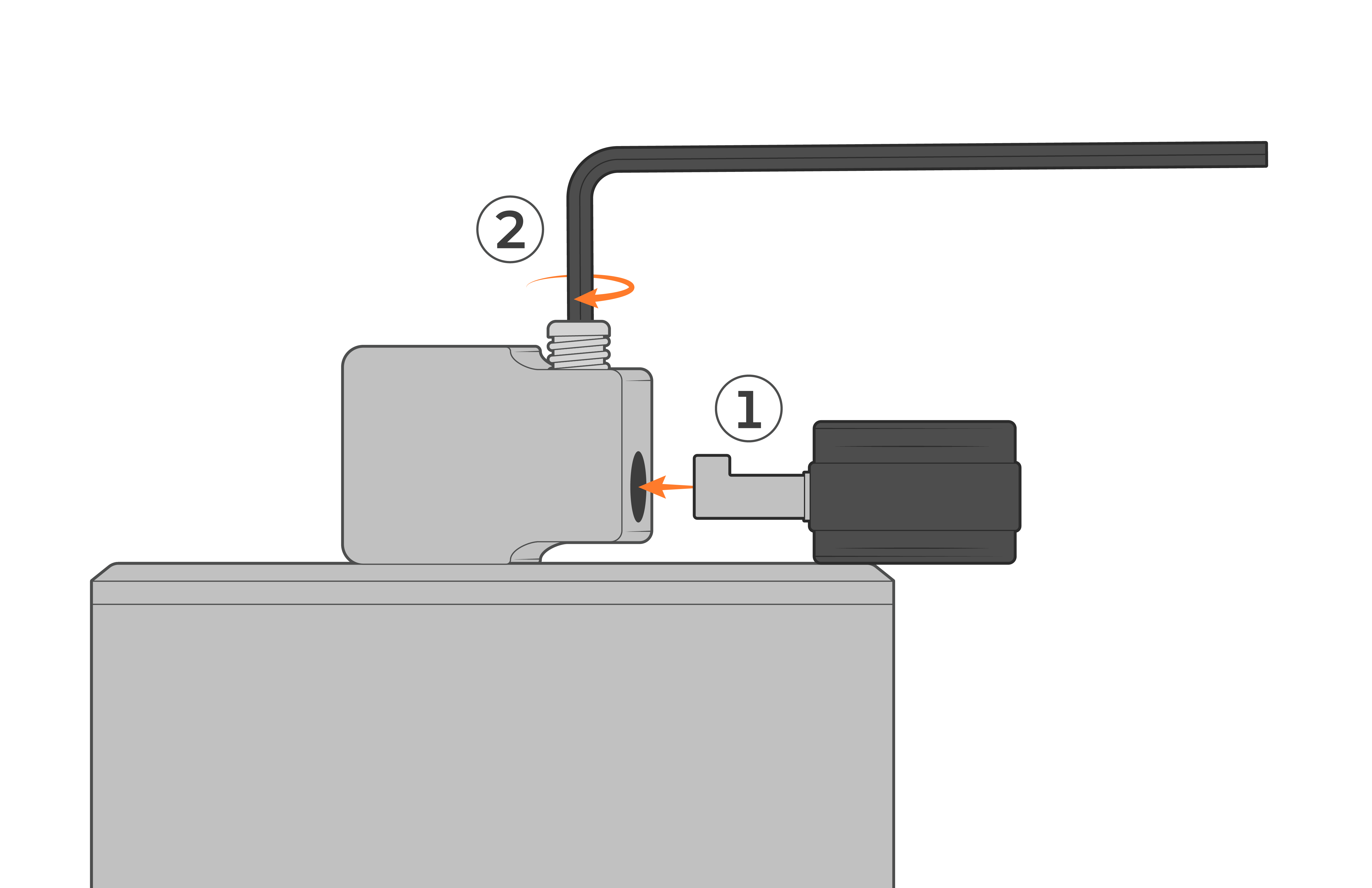
- Using the included Allen wrench, loosen the top screw.
![Angular view of the NX260 sensor-face. An Allen wrench is unscrewing the top screw. There are text notes that say "unscrew [only] until wiper is loose" and "hold wiper in place while unscrewing"](https://www.nexsens.com/wp-content/uploads/2025/09/NX-260__WiperReplacement_Fig2.png)
![Angular view of the NX260 sensor-face. An Allen wrench is unscrewing the top screw. There are text notes that say "unscrew [only] until wiper is loose" and "hold wiper in place while unscrewing"](data:image/svg+xml,%3Csvg%20xmlns=%22http://www.w3.org/2000/svg%22%20viewBox=%220%200%20440%20285%22%3E%3C/svg%3E)
- Once loosened, remove the old wiper.
- Insert the new wiper, divot facing up toward the set screw on the bracket, then tighten it in place.
9. Troubleshooting
Troubleshooting NX260 problems is best done by first connecting the sensor to NexSens CONNECT software.
| Error or Problem | Potential Causes | Solutions |
|---|---|---|
| Wiper parked over optics | Sensor powered off during cleaning cycle. Sensor failure |
Unplug and reconnect the power. The sensor wiper will reset. Contact NexSens support |
| Internal damage | — | Contact NexSens support for return instructions. |
| Negative turbidity readings | Sample clearer than 0 FNU calibration reagent Sensor optical signal receiving stray or ambient light during calibration |
Be sure to use a clean 0 FNU cal reagent. Center the sensor in an amber bottle, a minimum of 4 inches from the bottom, during calibration |
| Sensor readings not updating | Communication failure | Check cable connections and power. Check if the wiper is turning. Check the Com port |
| Erratic readings | Air bubbles or debris on sensor face Sensor failure |
Visually inspect the sensor face. When returned to water, initiate a wipe cycle. Contact NexSens support |
| Calibration error | Erroneous calibration constants | Uncal and recalibrate |
10. NexSens Warranty
View the NexSens Warranty.
11. NexSens Service Request
To return equipment for evaluation and repair, visit this page for more information.
Appendix A
RS-485 Modbus wiring pinout and commands.
| Register Address (Hex) | # of Registers | Name | Access | Limits or Range | Units | Data | Function Code | Comments | Test Request | Test Response |
|---|---|---|---|---|---|---|---|---|---|---|
| 12288 (0x3000) | 1 | Get/Set Modbus Device address | Read/Write | 1-247 | — | 16-bit integer little endian | 03, 16 | Use Get command with universal address 255 (0xFF) | FF,03,30,00,00,01,9E,D4 (Get Slave ID) |
FF,03,02,03,00,91,60 (Slave ID) |
| 1792 (0x0700) | 2 | Get Software and Hardware Revision | Read Only | — | — | 16-bit unsigned | 03 | Register 1 = Hardware Register 2 = Software |
01,03,07,00,00,02,C5,7F | 01,03,04,01,07,03,01,8B,3E (HW: 1.07, SW: 3.01) |
| 2304 (0x0900) | 7 | Get SN | Read Only | — | — | ASCII | 03 | Byte 0: Reserved Byte 1–13: 12 character null terminated ASCII string serial number |
01,03,09,00,00,07,07,94 | 01,03,0E,29,59,4C,32,39,32,34,30,31,30,38,30,31,00,0C,7D (YL2924010801) |
| 9472 (0x2500) | 1 | Start Measurement | Read Only | — | — | 16-bit integer little endian | 03 | By default, measurements will output every second. | 01,03,25,00,00,01,8F,06 | 01,03,02,00,00,B8,44 |
| 11776 (0x2E00) | 1 | Stop Measurement | Read Only | — | — | 16-bit integer little endian | 03 | — | 01,03,2E,00,00,01,8D,22 | 01,03,02,00,00,B8,44 |
| 9728 (0x2600) | 5 | Get Temperature and Turbidity Values | Read Only | Temperature: °C Turbidity: FTU |
Floating point (Little endian) | 03 | Register 1–2: Temperature Register 3–4: Turbidity Register 5: Error flag |
01,03,26,00,00,05,8E,81 | 01,03,0A,A0,5F,B9,41,78,7B,9C,41,00,00,95,EB Temperature = 23.17°C (0x41B95FA0) Turbidity = 19.560287 (0x419C7B78) Error Flag = 0 (0x0000) |
|
| 4352 (0x1100) | 4 | Get/Set User Calibration Coefficients | Read/Write | — | — | Floating point (Little endian) | 03, 16 | Register 1–2: K Value Register 3–4: B Value |
01,03,11,00,00,04,41,35 (Get calibration coefficients) |
01,03,08,00,00,80,3F,00,00,00,00,9E,12 K-value: 1.00 (0x3F800000) B-value: 0.00 (0x00000000) |
| 6912 (0x1B00) | 1 | Brush power-on startup settings | Write Only | — | — | 16-bit integer little endian | 16 | 0x0000: Does not start on power 0x0100: Power on and self-start |
||
| 12544 (0x3100) | 0 | Activate Wiper | Write Only | — | — | 16-bit integer little endian | 16 | The wiper will make four rotations in each direction. | 01,10,31,00,00,00,00,74,94 | 01,10,31,00,00,00,CE,F5 |
| 12800 (0x3200) | 1 | Get/Set Wiper Interval | Read/Write | — | — | 16-bit integer little endian | 03, 16 | 01,03,32,00,00,01,8A,B2 (Get wiper interval) |
01,03,02,1E,00,B1,E4 |