
Direct Connect to an iSIC Data Logger
A UW-USB-485P cable can be used to establish a direct connection with a SDL500C, SDL500R or SDL500I data logger.
1. Plug the USB cable into a computer and verify the COM port of the cable.
2. Open iChart.
3. Select Advanced | Terminal from the file menu.

Figure 1: Advanced | Terminal
4. Select the COM Port to which the USB cable is connected.
5. Select Direct Connect as the Connection type.
6. Uncheck the “Use iSIC” box.

Figure 2: Verify COM Port, select Direct Connect and uncheck “Use iSIC”
7. Click Connect.
8. Remove any power sources such as external or internal batteries from the submersible data logger.
Note: These can be re-connected if needed to power a sensor after communication is established. However, the power must be cycled in order to establish communication so all other power sources must be removed.
9. Plug the cable into the top port of the SDL.

Figure 3: Top/COM Bulkhead of SDL500
a. For SDL COM bulkheads built with a coaxial RF receptacle pin, make sure the USB communications cable used lacks the corresponding male pin (see below). Otherwise this pin can be come damaged from attempting the connection.
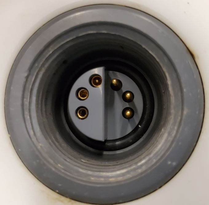
SDL COM bulkhead with newer-style coaxial RF receptacle pin.
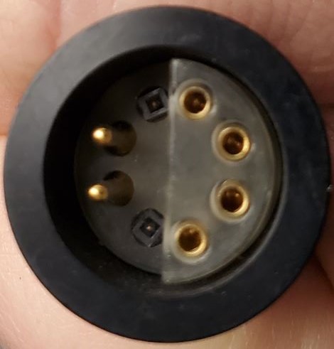
UW-USB-485P COM cable with removed pins for connection to SDLs with coaxial RF-equipped top bulkhead.
10. When “NexSens iSIC” appears in the terminal window, hit the ESC key and type 485.
a. Note: This must be done within 1-2 seconds of the message appearing.
b. If the 485 break is not entered at a proper time (or it is not accepted) disconnect the COM cable and wait a couple of seconds before re-connecting and trying again.
b. If no message appears, disconnect the cable from the SDL and install D-cell batteries or apply 12V power through sensor port D or P0. At the same time external power is applied, re-connect the communications cable. Certain USB ports output slightly less power than is required to power the iSIC and supplying 12V power can allow the system to bootup normally.
11. A message similar to the following should appear. Note that the first line should read the type of data logger being used, so for example: “NexSens 3100-iSIC” should appear if a 3100-iSIC is used or “NexSens SDL500R” if an SDL500R logger is used.
%232
%485

Figure 5: Terminal Output for Temporary RS-485 Communication
12. Close the terminal window.
The iSIC will now communicate in RS-485 until power is cycled or until the top of each hour when the SDL completes a diagnostic soft reset.