
How to Install a 4G Modem in a 3100-iSIC
Prior to installation, be sure that the new 4G cellular modem has a SIM card installed and its account is active.
1. Open up the 3100-iSIC enclosure and remove both fuses by pressing down on the holder cap and turning it counterclockwise.
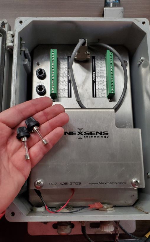
Remove External and BAT fuses to disconnect power.
2. Use a large Phillips screwdriver to remove the four primary mounting plate screws.
Remove Upper Mounting Plate Screws.
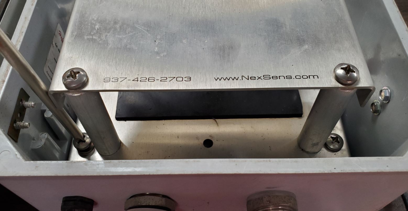
Remove Lower Mounting Plate Screws.
3. Lift up the mounting plate and invert to access the back side.
Turn over the mounting plate to access the components on the back side.
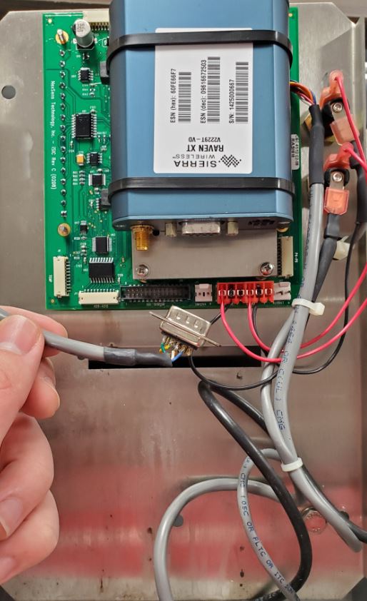
4. Remove the old modem power cable unless the existing modem is a Sierra Wireless LS300 model.
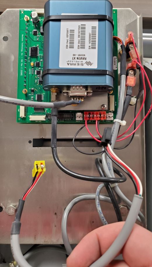
Removing the original modem power cable from a Raven XT modem (as shown).
5. Use a 5/16″ or adjustable crescent wrench to carefully loosen the SMA-type RF cable from the original modem.
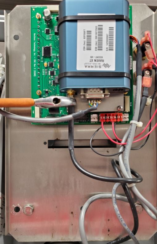
Turn SMA connector counterclockwise to loosen the RF cable.
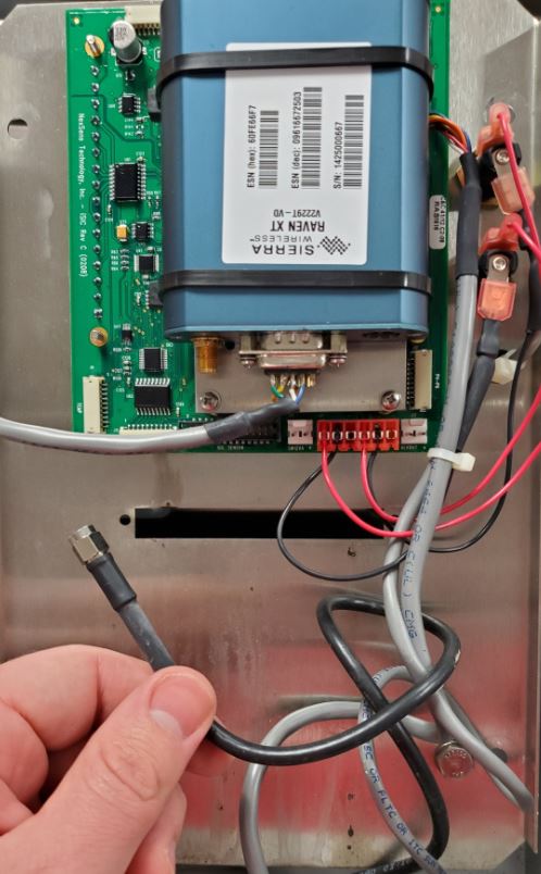
RF Cable Removed.
6. Use a Phillips screwdriver to remove the screws securing the serial cable to the original modem.
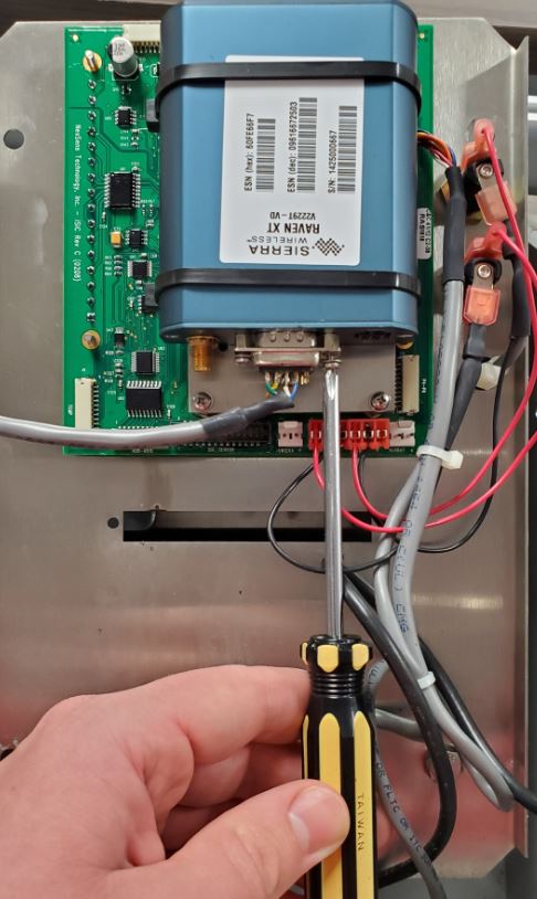
Remove DB9 Serial Connector screws.
7. Disconnect the serial cable by gripping the connector. Pulling on the cable may damage the soldered wire connections.
Disconnected Serial Cable.
8. Cut the zip ties affixing the original modem to the small mounting plate and remove the modem.
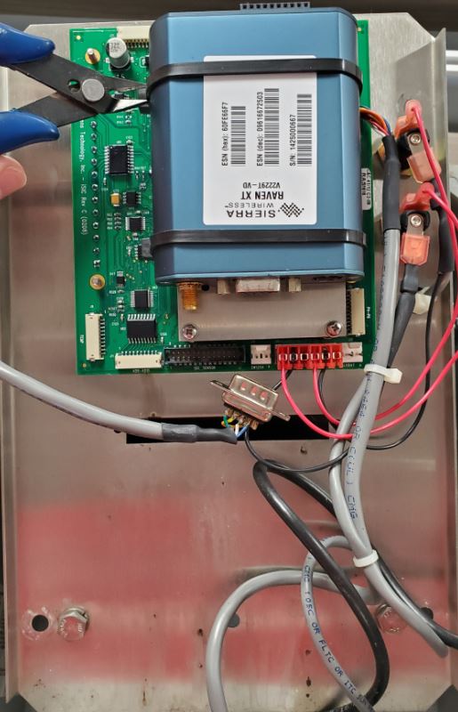
Cut Zip Ties.
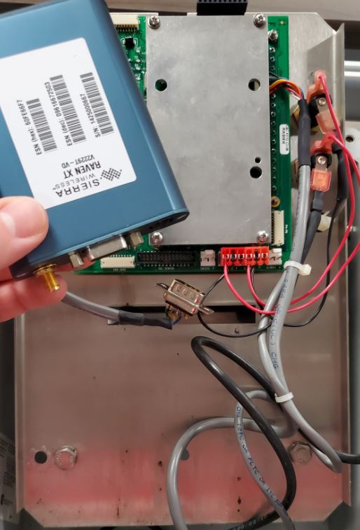
Remove old cell modem.
9. Use velcro strips to secure the new 4G modem to the plate.

Apply velcro backing to modem mounting plate.

Position the new modem such that its connectors face the same direction as the original modem’s.
10. Connect the new modem power cable (or existing if replacing an LS300 model 3G modem).
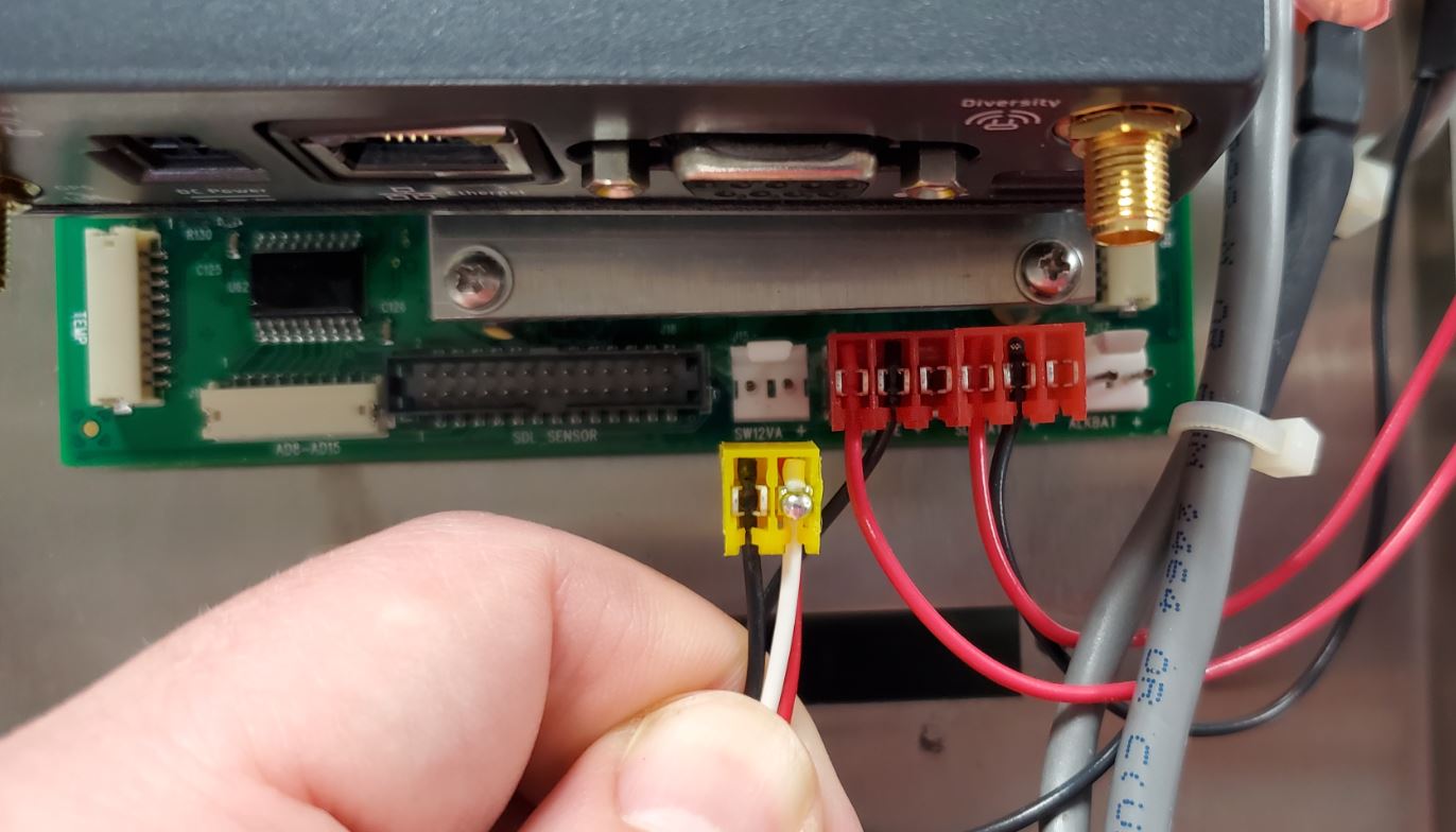
Connect the yellow power cable connector to the data logger PCB’s ‘SW12V’ port.
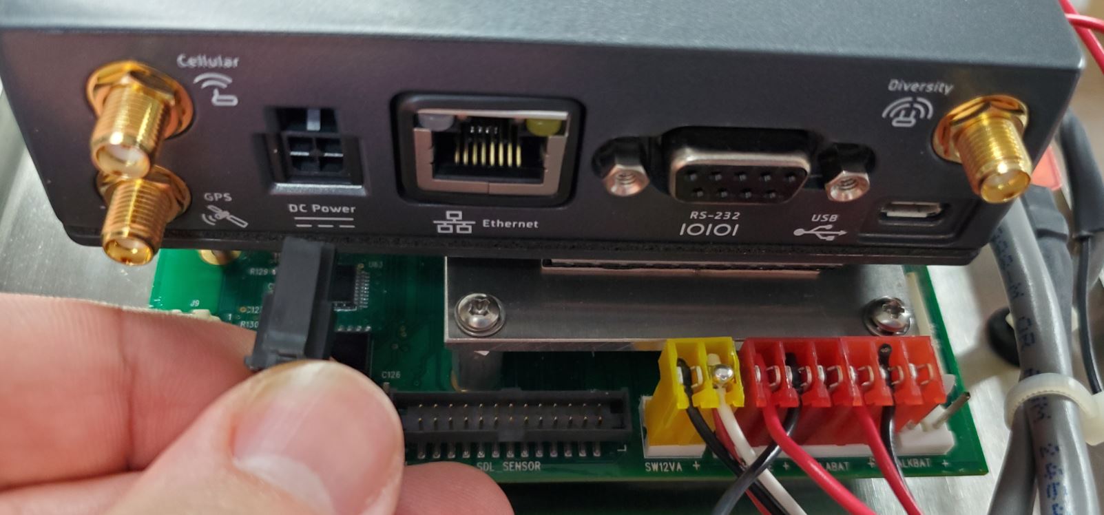
Connect the black-end of the power cable to the new modem’s ‘DC Power’ port.
11. Connect the DB9 serial cable connector to the new modem.
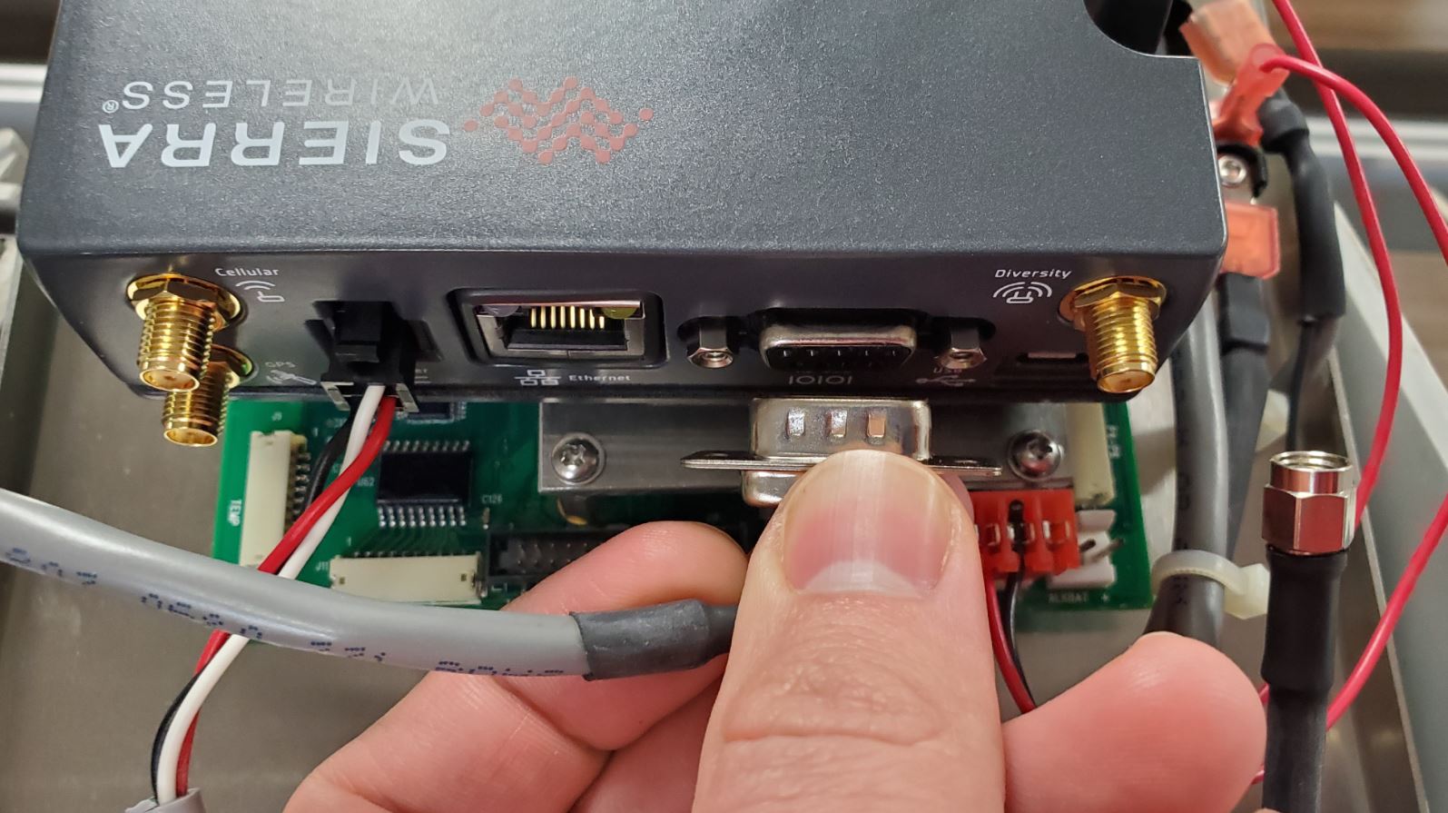
Connect the serial cable to the modem RS-232 port.
Secure the DB9 connector in place using the original Phillips-head screws and lockwashers.
12. Connect the SMA-type RF cable to the modem coaxial port marked ‘Cellular’. Ensure the connection is hand-tight before following up with a slight 1/8 rotation using a wrench. Do NOT over tighten.
Connect RF cable to ‘Cellular’ port.
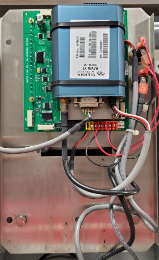
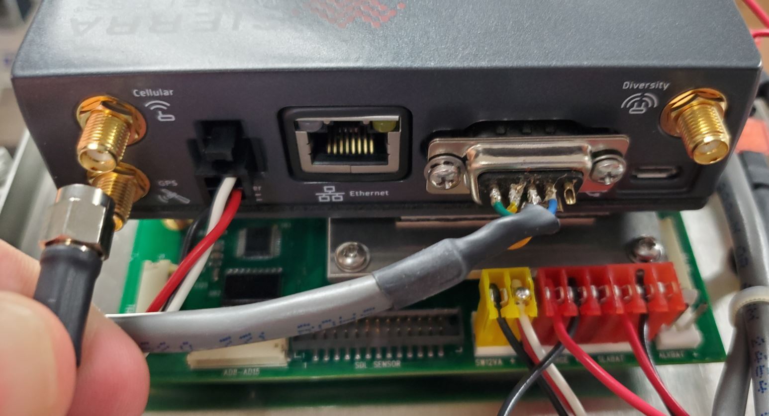
13. Verify the modem connections shown below have been made.
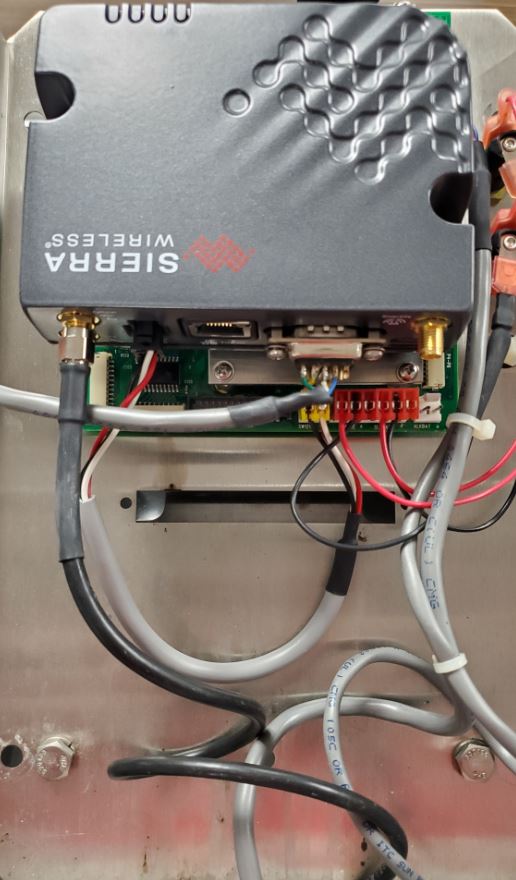
Completed modem installation.
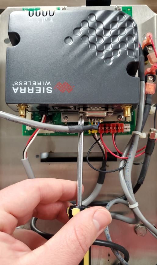
14. Invert the plate and place it back on the enclosure standoffs. Ensure that no cables are being pinched or pressured before re-installing the large plate screws.
Tighten the mounting plate screws back into the enclosure standoffs.
15. Re-install the BAT followed by the External fuse to re-apply power to the system.