
Checking Sensor Parameter Readings Using SDI-12
If iChart ever reads data input by a sensor as “-100000” it will be necessary to verify if the sensor is reading incorrectly. The problem may be elsewhere and completing these steps may rule out sensor failure and save on costly repairs.
- Make sure the sensor is connected and adequate power is applied to the data logger.
- Open iChart with the current project.
- Click Advanced | iSIC | iSIC. The iSIC Setup window should appear.
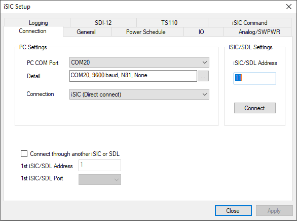
iSIC setup window
- Enter the correct connection type and iSIC or SDL address. If connecting directly to the iChart PC, make sure the correct COM Port is selected.
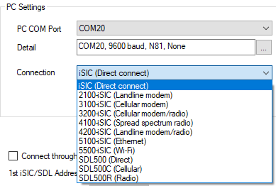
Available connection types for multiple iSIC logger models.
- Click Connect.
- Select the General tab to allow the iSIC’s configuration to be read.
- Select the SDI-12 tab.
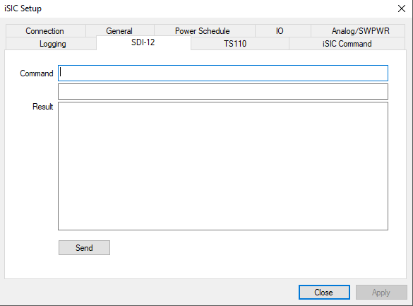
SDI-12 tab
- To find the sensor’s SDI-12 address, type this command:
“?!”
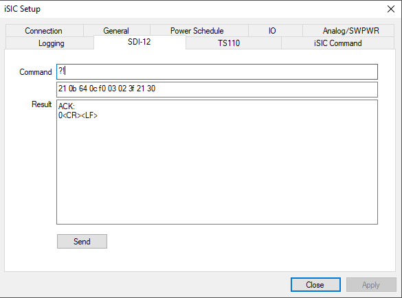
Address query command
-
- A result in this format should appear:
“a<CR><LF>”
-
- Note: “a” is used as an example address above. Record the sensor’s actual address. It will be used in sending other commands.
- Ensure that you are communicating with the correct sensor by inputting the identification command:
“aI!”
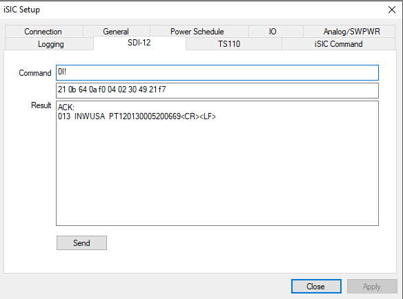
Sensor identification command
-
- A result should appear in this format:
“allccccccccmmmmmmvvvxxx . . . xxx <CR><LF>”
-
- Note: “a” is used as an example address above. “ll” is the SDI-12 version number indicating SDI-12 version compatibility. “cccccccc” is an 8 character vendor identification. “mmmmmm” is the sensor model number. “vvv” is the sensor version. “xxx…xxx” is an optional field, up to 13 characters” used for a serial number.
- Send this command:
“aM!”
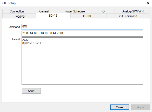
Measurement command
-
- A result should appear in this format:
“atttn<CR><LF>”
-
- Note: “a” is used as an example address. “ttt” is the number of seconds the sensor needs to take a reading. “n” is the number of parameters the sensor reads.
- After waiting “ttt” seconds, send this command using the sensor’s actual address:
“aD0!”
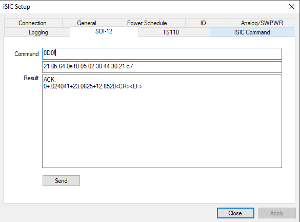
Data acquisition command
-
- A result should appear in this format:
“a<values><CR><LF>”
-
- Note: “<values>” are the parameters. Each one will be separated by a plus sign (+).
- Send “aDn!” to receive the remaining parameters.
-
- Note: “a” is the sensor address and “n” is 1 to 9 (aD1!, aD2!, aD3!…).
- Depending on the sensor, the number of parameters will be split between the different commands. For example, if a sensor outputs 9 parameters, the first 4 or 5 will be accessed by inputting the aD0! command, while the rest may be accessed in the subsequent aDn! commands until all the parameter values have been displayed.
- If only the sensor address is returned from an aDn! command, then there are no more parameter values available, and the former aDn! commands should contain the parameter values.

Since this sensor only outputs three parameters, all of the values will display in the 0D0! command and only the address will display in the 0D1! command.
- Verify that each parameter is not out of range. It may be beneficial to write each parameter reading down for verification.