
How do I check continuity in a sensor cable?
If a sensor is unresponsive or giving intermittent readings, follow this article to check cable signal continuity and confirm resistance is within specifications. All signals in NexSens cables should measure less than 1 Ω.
Measure Cable Resistance
- Connect the red lead (positive) to the port marked V or Ω.
- Connect the black lead (negative) to COM.
- Set the dial to the Ω symbol.
- Note: Markings and connectors may vary depending on the brand/model of the multimeter.
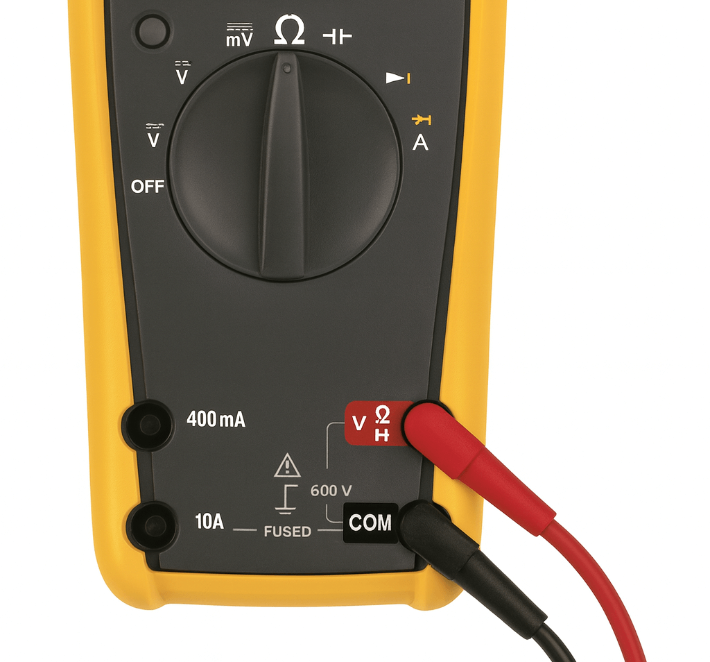
Figure 1: Multimeter settings to check cable resistance.
- Touch the red and black leads together to establish a baseline reading. This reading will be used to account for background resistance in the multimeter.
- Review the sensor cable pinout.
- Place one lead on each end of the cable pins corresponding to the same signal.
- Subtract the baseline value gathered earlier from the measured resistance shown on the multimeter.
- The resistance should be equal to or less than 1 Ω.
- Repeat for all signals.