
Replace RF-Cable Assembly
In the event of damage, the RF cable assembly on the X2 data logger can be replaced.
Caution!!!- Be sure to statically ground yourself prior to touching any of the electronics inside the X2 logger!
Tools Required:
- Phillips Head Screwdriver
- 3/16″ Hex Driver or Adjustable Wrench
- 5/8″ Socket
Instructions
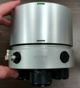
- Locate the green plastic wire from its track in the base of the X2’s aluminum housing.

Locate the green wire holding the X2 housing in place.
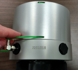
- Slide tweezers or the tip of the screwdriver packaged with the X2 beneath the wire to expose it.
- Pull the end of the wire while applying pressure to the top of the X2 to remove it from the track. Tweezers or needle-nose pliers can be used if needed.
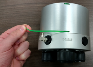
Pull the green wire completely out of the housing.
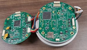
- Pull up on the enclosure to separate it from the X2 base.
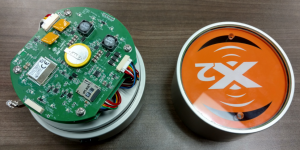
Separate the enclosure and the bulkhead.
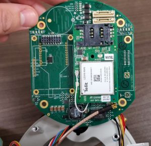
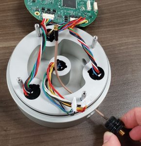
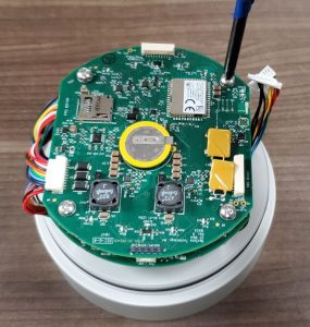
- Press down on the tabs of the upward-facing UW6 Direct and downward-facing UW6 RTU JST connectors and gently pull to remove them from the main PCB.
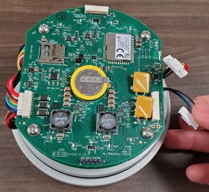
Remove the UW6 JST connectors.
- Remove the four visible Phillips-head screws and lock washers from the top of the main PCB.
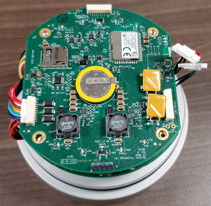
Remove the Phillips head screws.
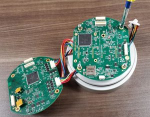
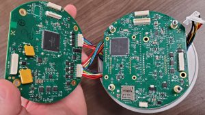
- Gently lift up on the PCB to disconnect the board-to-board connector and expose the RTU PCB.
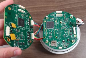
Separate the main and RTU boards.
- Use a 3/16″ nut driver or adjustable wrench to remove the four standoffs that hold the RTU PCB in place.
Remove the standoffs holding the RTU board.
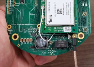
- Tip the RTU PCB to reveal the gold MMCX RF connector.
X2 RF connector.
- Pull upwards on the MMCX connector to remove it from the P2 port on the RTU PCB.
Remove MMCX connector.
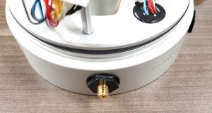
- Use a 5/8″ socket to loosen the cable assembly port by hand.
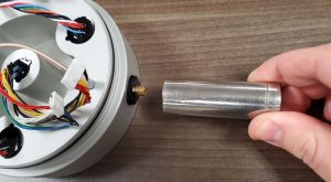
Loosen cable assembly port.
- Remove the old assembly from the X2 housing.
Remove RF assembly.
- Evenly spread O-ring grease onto the replacement cable assembly’s O-ring.
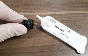
Apply grease to O-ring.
- Use the 5/8″ socket to tighten the new RF cable into the port. Ensure the other end of the cable is free to turn with the port.
Tighten new RF assembly before connecting to PCB.
- Once fully hand-tightened, the cable O-ring should not be visible.
Installed RF assembly.
- Align the MMCX connector of the new cable with the P2 port on the RTU board. Press downward firmly until a click is felt signifying a secure connection.
Installed MMCX connector.
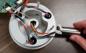
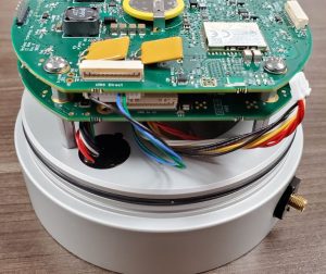
- Pivot the RF cable such that it runs along the full length of the modem.
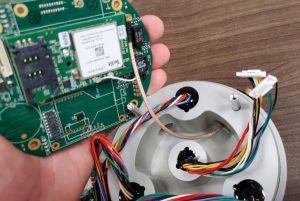
Align RF cable.
- Place the RTU PCB back on top of the base and hand tighten the four standoffs back in place. Follow up with an additional 1/8 of a turn using the nut driver or adjustable wrench.
Reinsert the standoffs.
- Align the board-to-board connector and place the main board back on top of the RTU board, pressing down gently until the connector locks into place.
Reconnect the RTU and main boards.
- Tighten the top PCB back in place using the four Phillips screws and lock washers.
Reinsert the Phillips head screws.
- Re-connect the UW6 RTU JST connector, gently pressing in until a click is heard.
Reconnect the UW6 RTU JST.
- Re-connect the UW6 Direct JST connector.
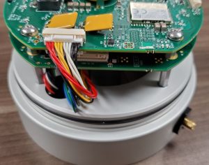
Reconnect the UW6 Direct JST.
- Slide the enclosure back over top the X2 base, ensuring that no wires are pinched in the process.
Push on the enclosure.
- Align the wire entry with the machined body tag on the aluminum base.
- Push down on the top of the enclosure and feed the wire back into its track.
Reinsert the green wire.