
Replace Desiccant
Each X2-CB/X2-CBMC ships with a bag of desiccant inside the logger enclosure. This desiccant bag should be replaced whenever:
- The X2-CB/CBMC enclosure is opened.
- The Internal Humidity diagnostic parameter reads 50% or greater.
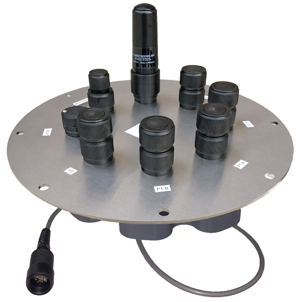
Figure 1: X2-CB data logger.
Caution!!!- Be sure to statically ground yourself prior to touching any of the electronics inside the X2 logger!
Any appropriately-sized silica gel desiccant pack (the included pack is 6″x 1.5″ for reference) or the NeSens A71 desiccant kit can be used for replacement.
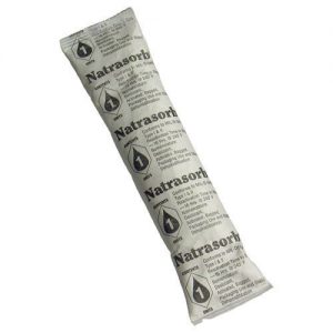
Figure 2: A71 desiccant kit.
Desiccant Replacement Process
- Disconnect the 6-pin solar panel or UW-6 USB cable from the X2-CB/X2-CBMC SOLAR/COM port to remove power from the data logger.
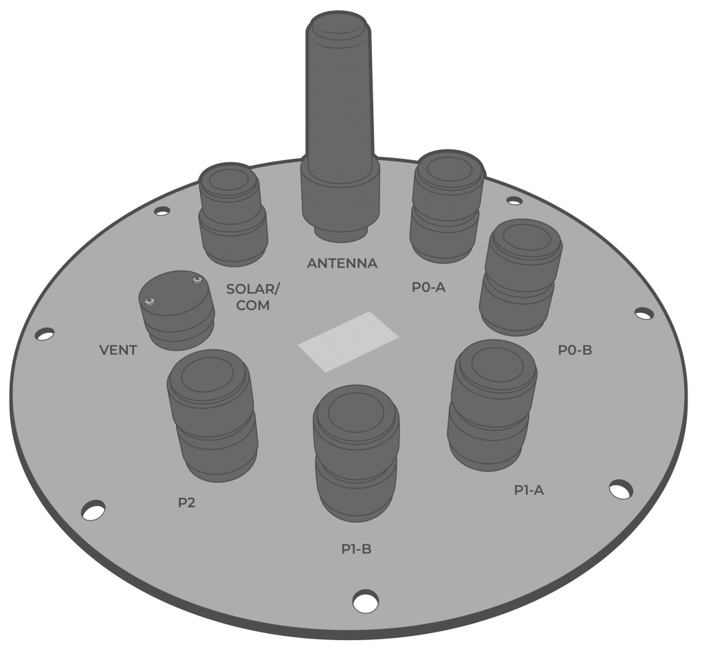
Figure 3: X2-CB port configuration. |
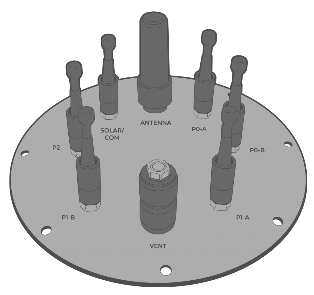
Figure 4: X2-CBMC port configuration. |
- [For CB-150/250/450 buoys only] Use a 9/16″ socket wrench to remove the (6) bolts holding the buoy’s solar tower to access the data well.
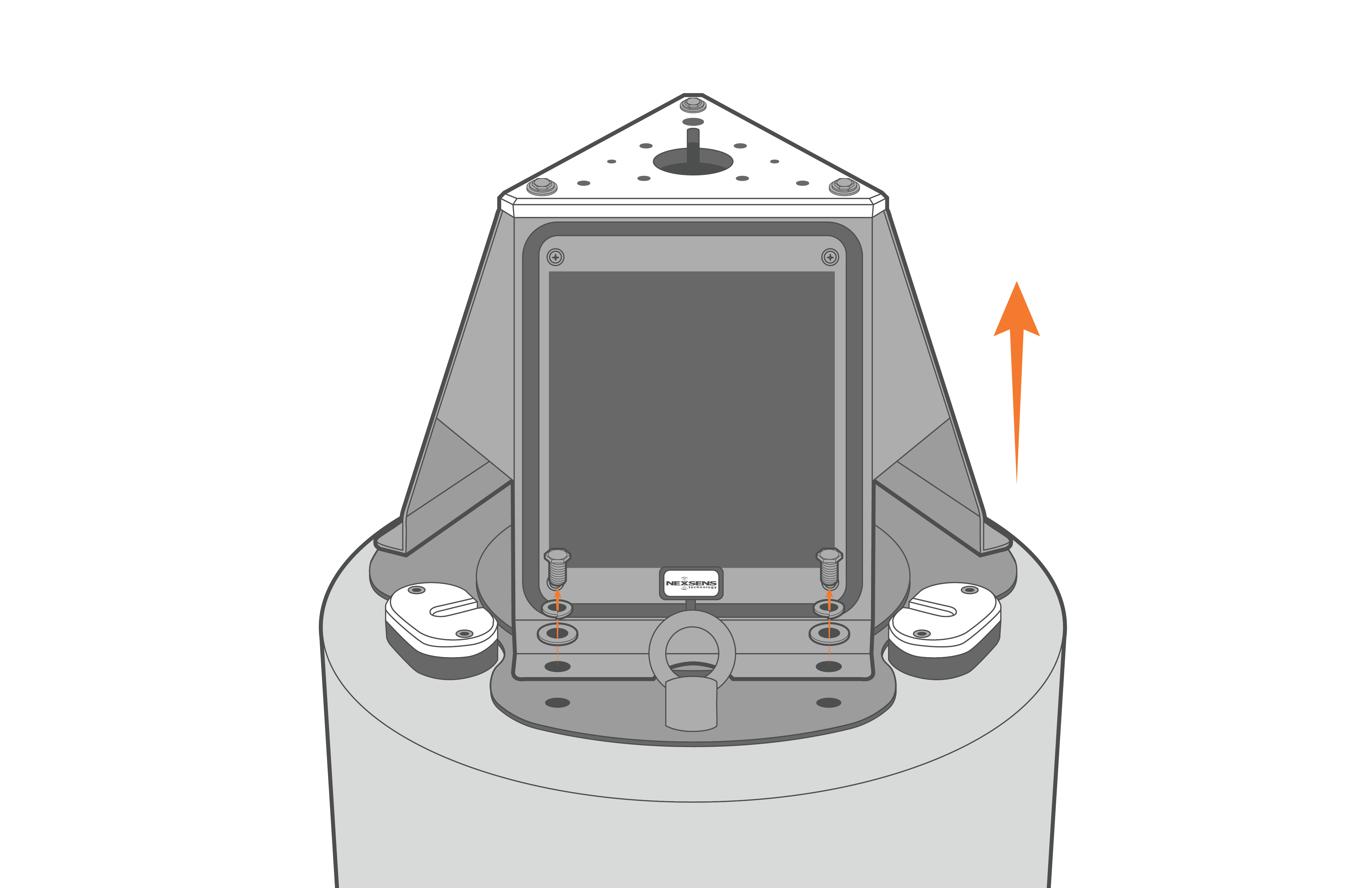
Figure 5: Remove solar tower from CB-150/250/450 buoys.
- Remove the (8) bolts from the X2-CB/X2-CBMC using a 9/16″ socket wrench.
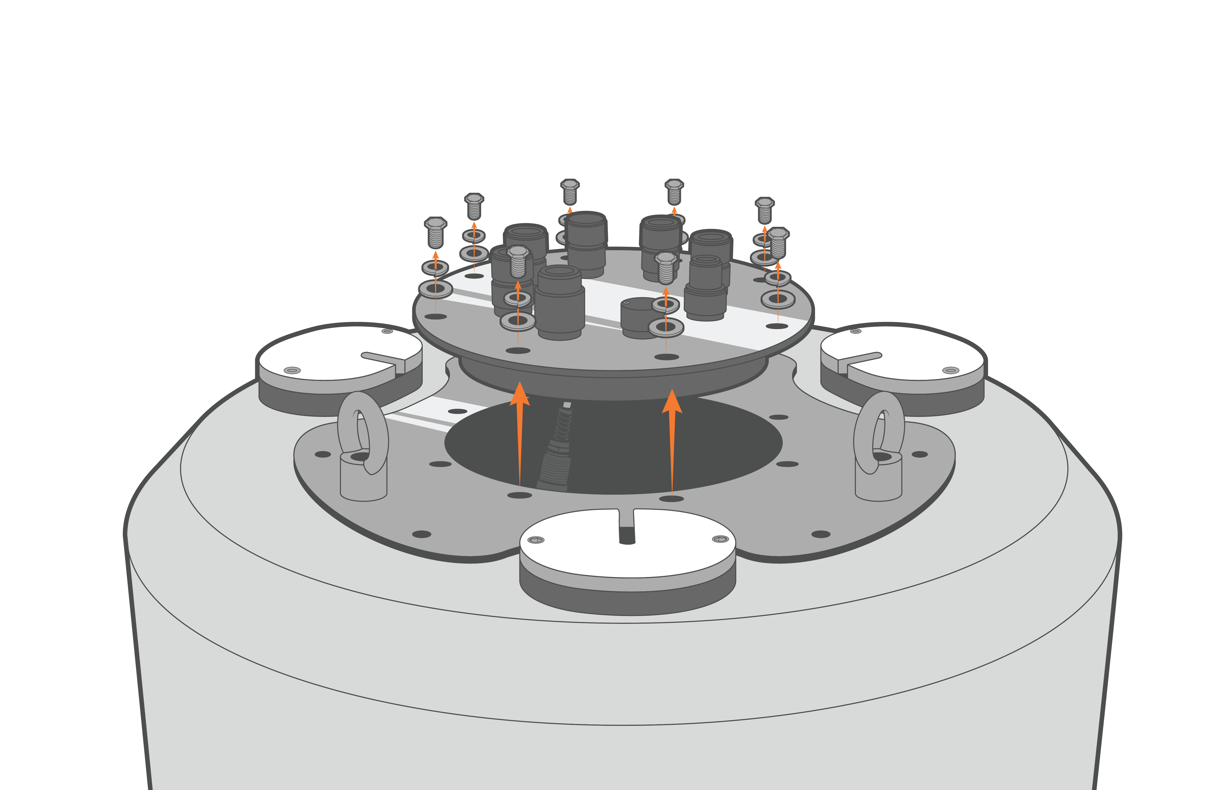
Figure 6: X2-CB removal from CB-150/250/450 buoys. |
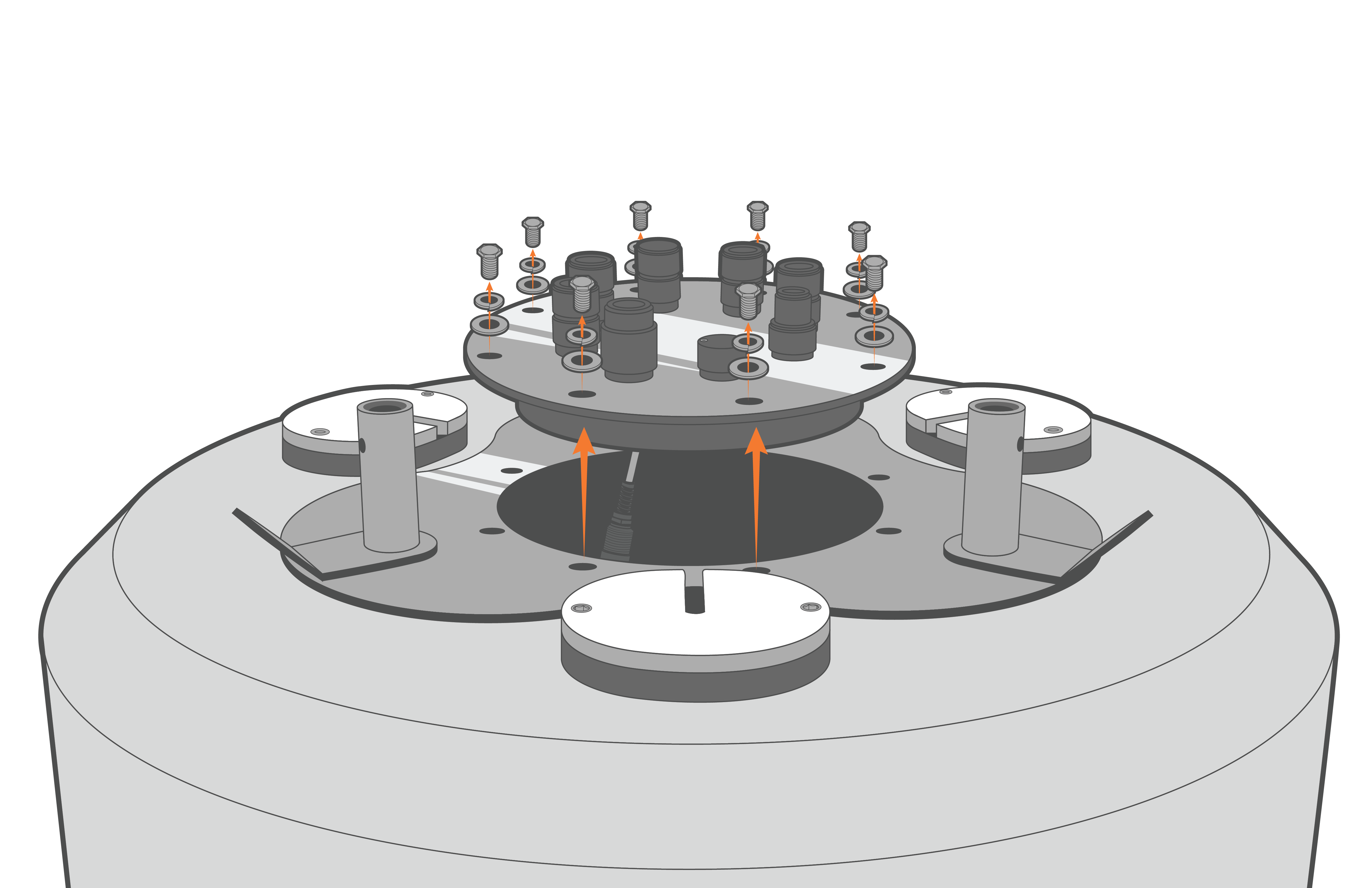
Figure 7: X2-CB removal from CB-650/950/1250 buoys. |
- Lift up the logger and disconnect the 6-pin plug connecting the battery harness to the bottom cable of the X2 logger.

Figure 8: Unplug X2-CB in CB-150/250/450 buoys. |

Figure 9: Unplug X2-CB in CB-650/950/1250 buoys. |
- Invert the logger plate and remove the (8) 8-32 x 1/2 screws holding the X2 enclosure to the metal plate using a Philips-head screwdriver.
- Gently lift the enclosure to expose the RTU PCB of the X2. Statically ground yourself prior to touching any of the electronics inside the X2 logger.
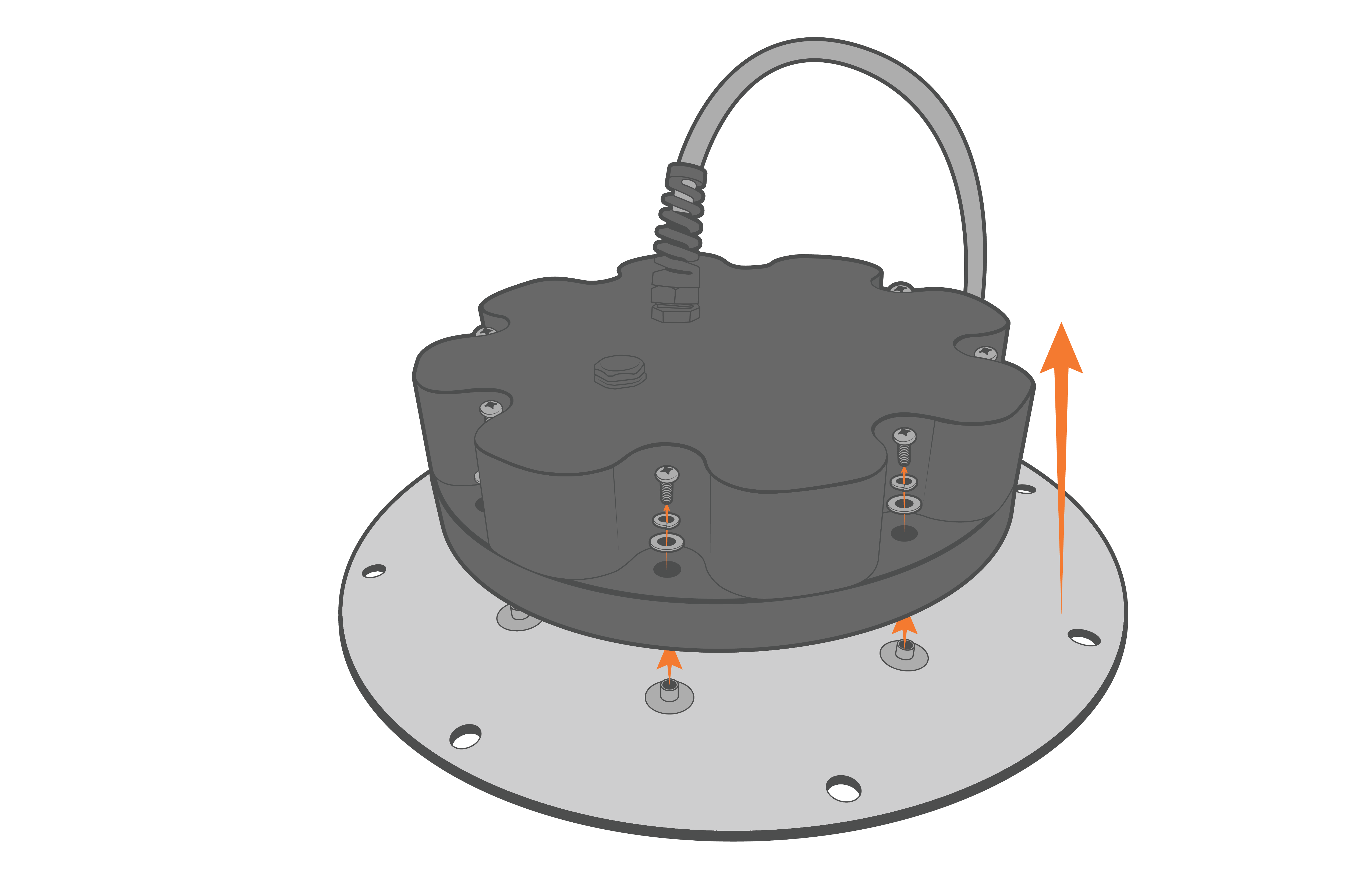
Figure 10: Remove the X2-CB/X2-CBMC housing screws.
- Disconnect the 4-pin Molex connector between the enclosure and the X2 data logger.
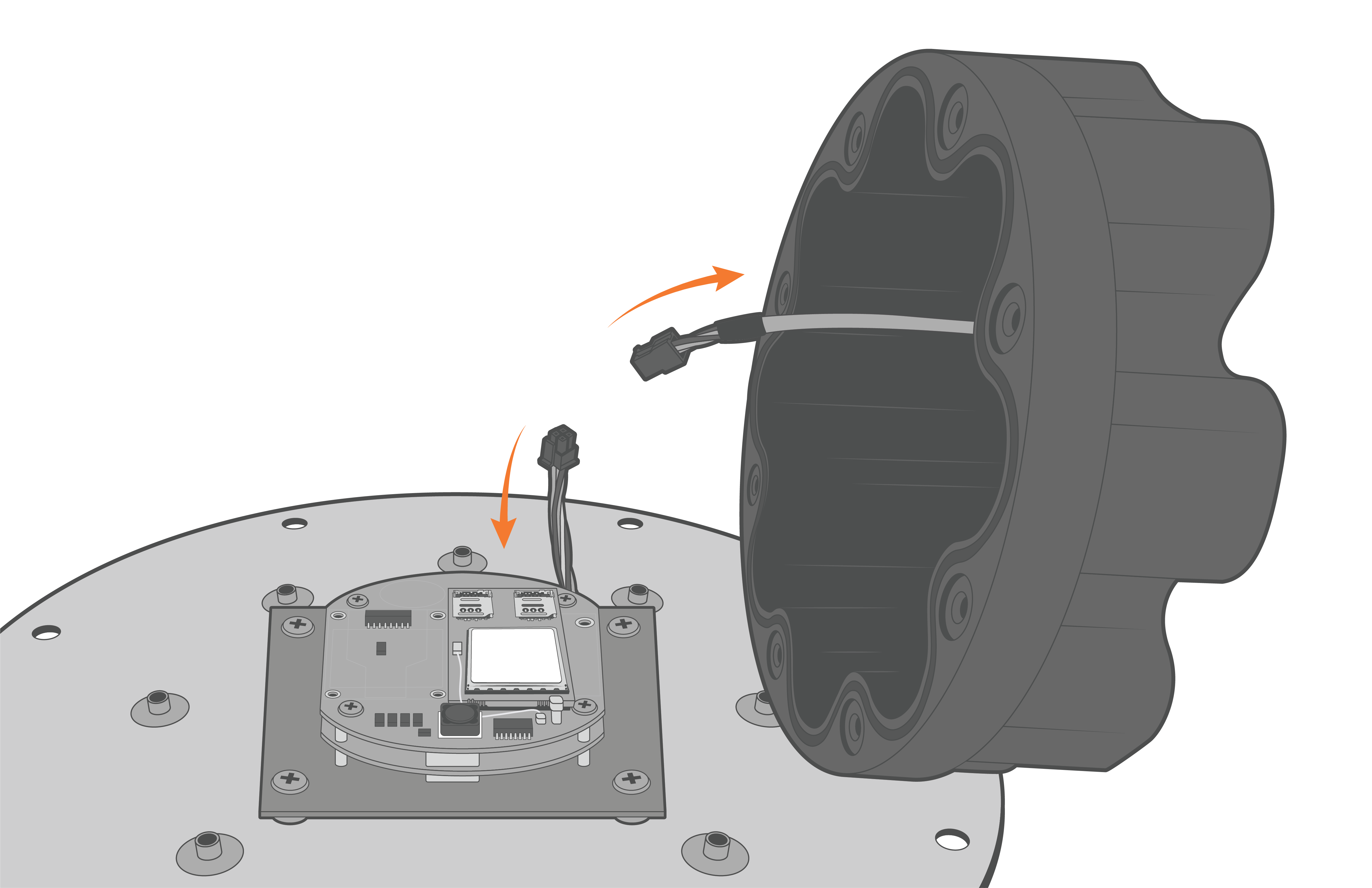
Figure 11: Disconnect the Molex power connector.
Replace the desiccant and re-assemble the X2-CB Housing
- Realign the O-ring within the grooves on the bottom of the X2-CB/X2-CBMC enclosure.
- Place the desiccant on the RTU board next to the modem.
- Orient the X2-CB/X2-CBMC enclosure such that the power cable feeding up through the bottom of the base lies flat when closed and is not above the cellular modem.
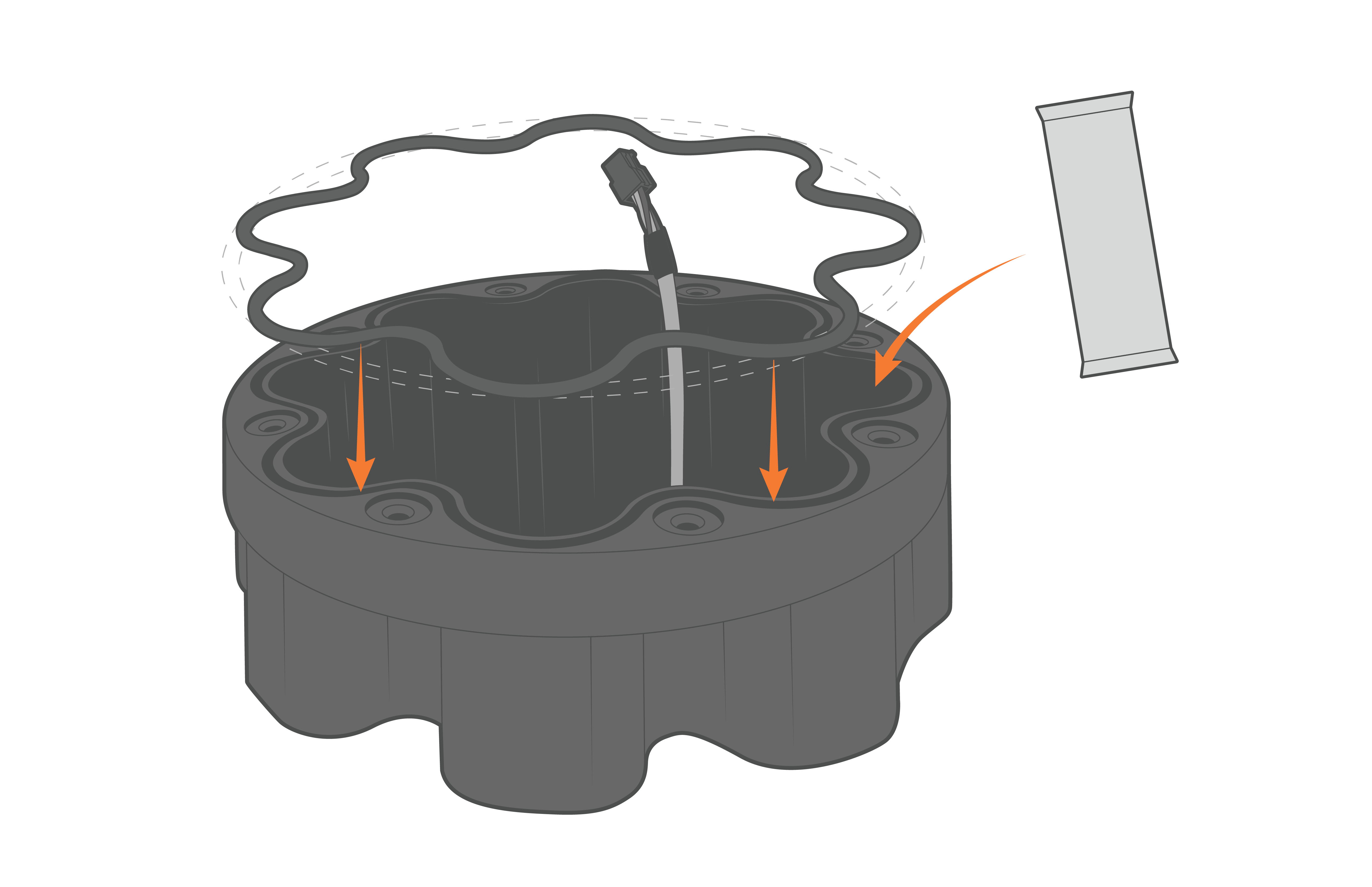
Figure 12: Re-align the O-ring and ensure to replace the desiccant. |
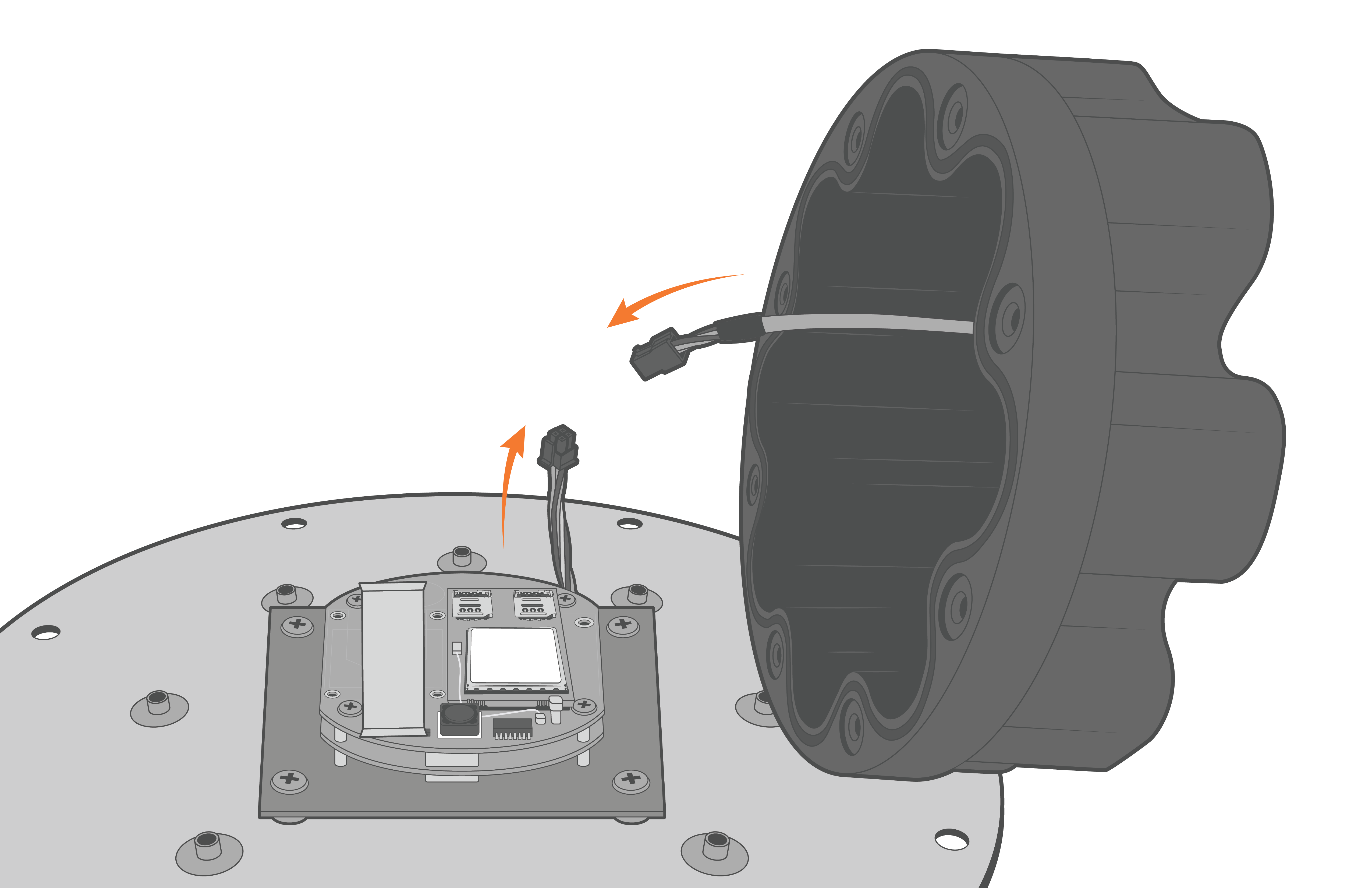
Figure 13: Reconnect the Molex power cable. |
- Align the holes on the enclosure with the threads on the plate. Ensure the large exterior O-ring is secure in its grooves and is making proper contact with the bottom of the logger plate.
- Thread the (8) 8-32 x 1/2 screws in halfway before tightening in a cross pattern with a Phillips Screwdriver.
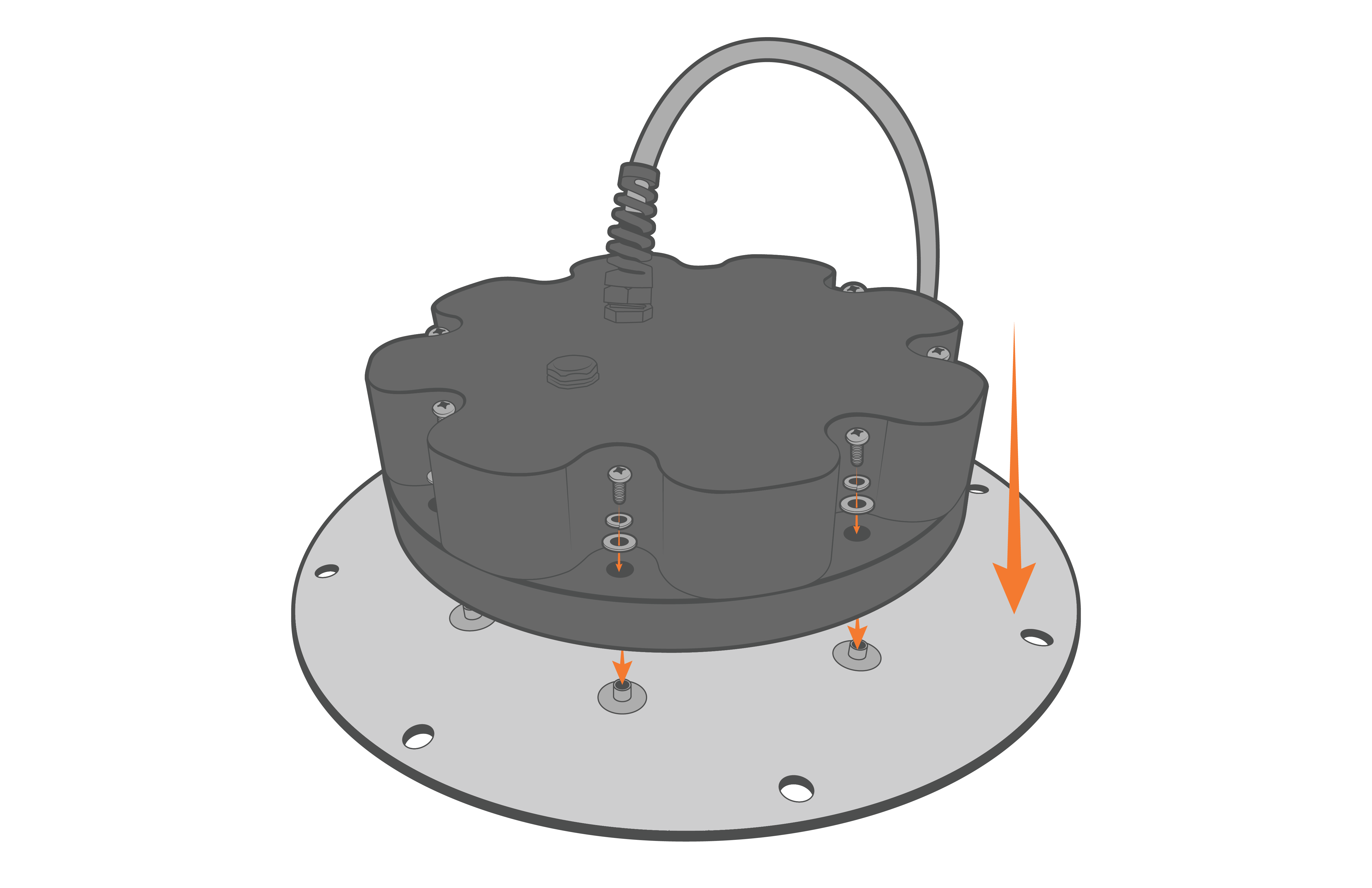
Figure 14: Re-install the X2-CB-X2-CBMC enclosure. |
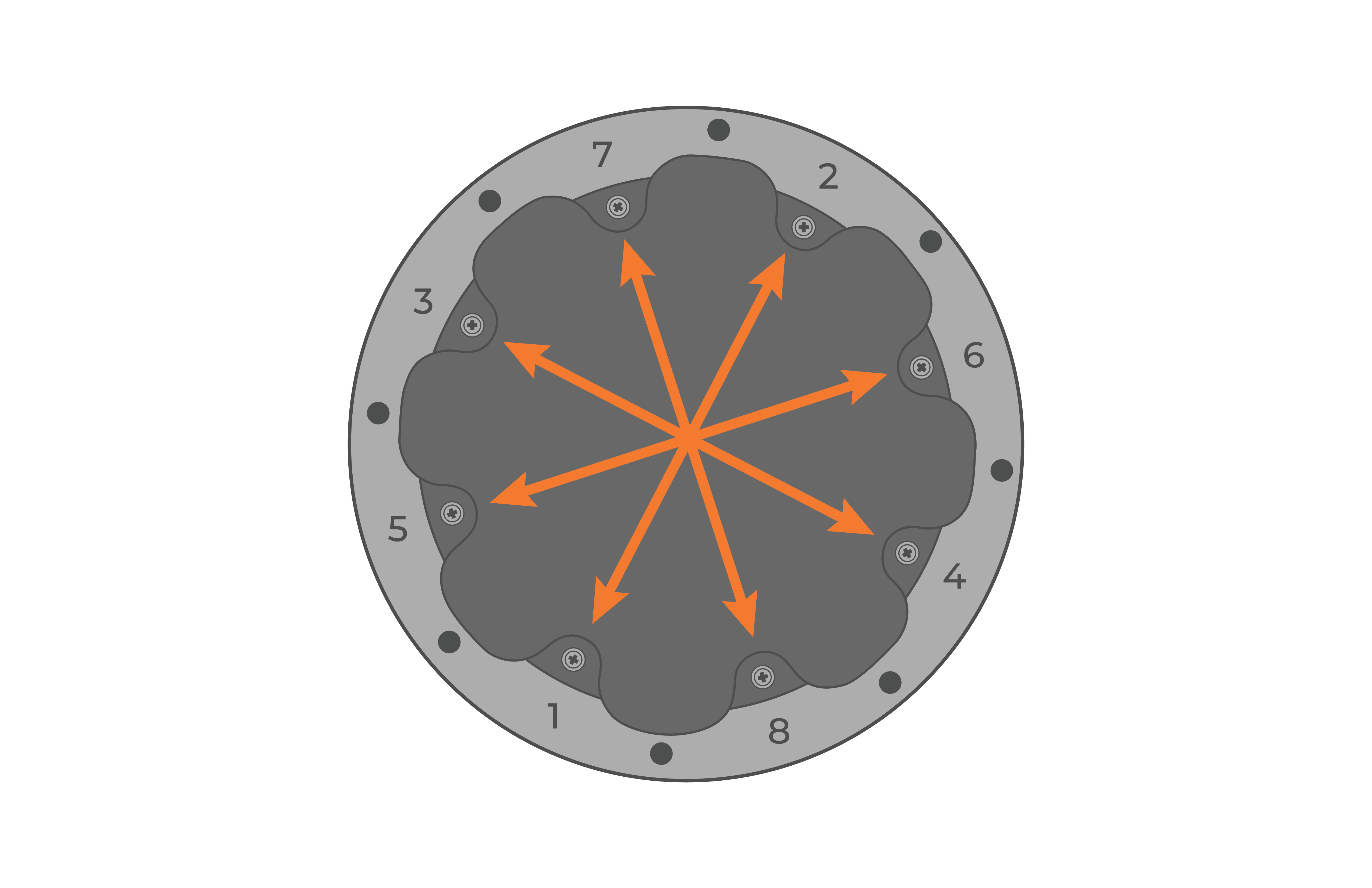
Figure 15: Evenly tighten the screws in a crisscross pattern. |
- Place the re-assembled X2-CB/X2-CBMC back on top of the data well.
- Ensure the primary O-ring is clear of debris and centered in the groove.
- It is recommended to replace the desiccant pack within the data well at this time.
- Reconnect the 6-pin plug on the bottom cable of the X2 logger to the battery harness cable.
- Ensure the primary O-ring is clear of debris and centered in the groove.
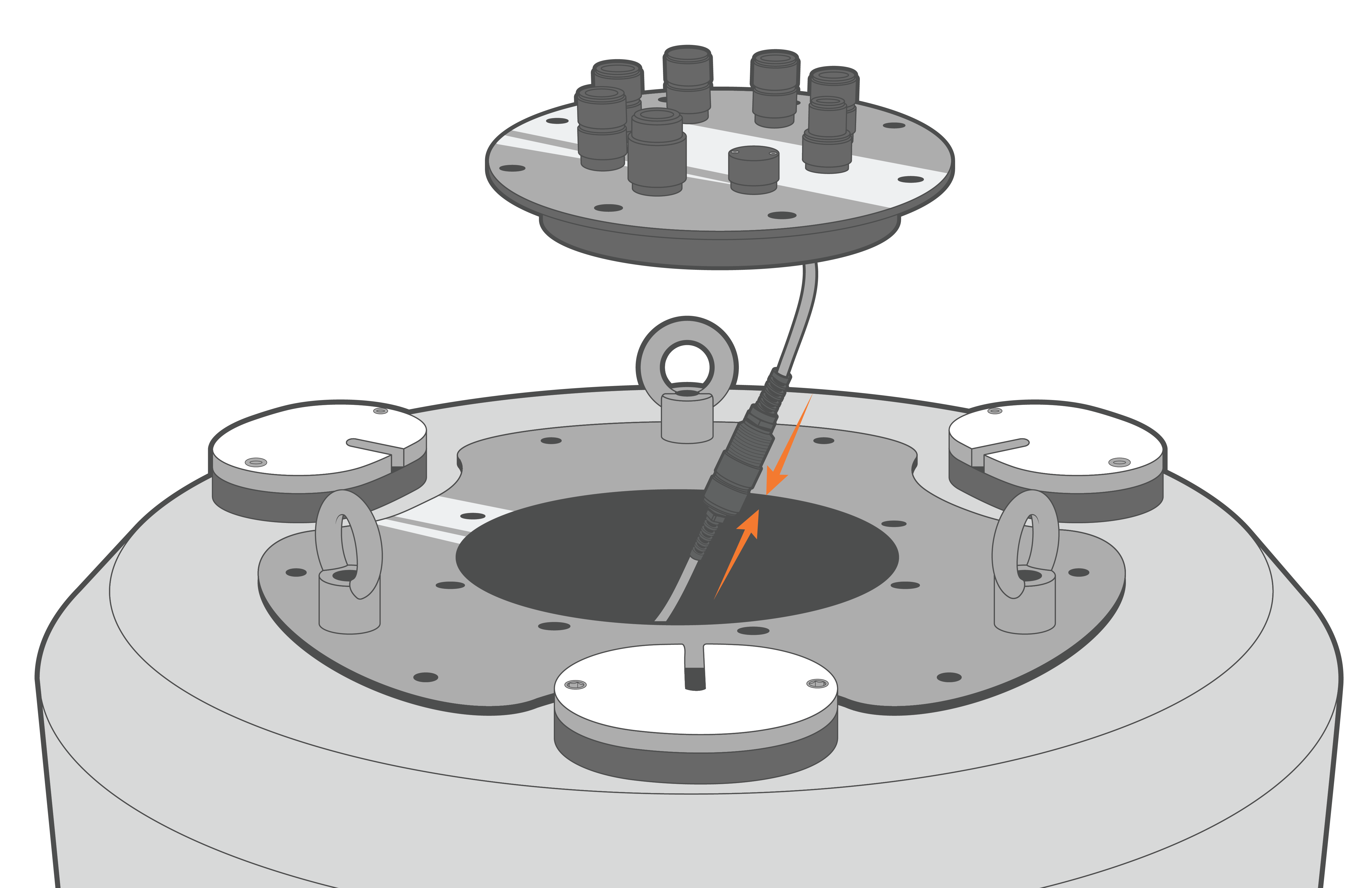
Figure 16: Re-connect the data well 6-pin cable connection.
- Align the plate and re-install the (8) bolts with lock washers, tightening them in a cross-pattern using a 9/16″ socket wrench.
- Orient the SOLAR/COM port towards one of the deployment tubes for easier access when the solar tower is installed.
- Ensure there are no substantial gaps between the data logger plate and the metal frame of the buoy data well.
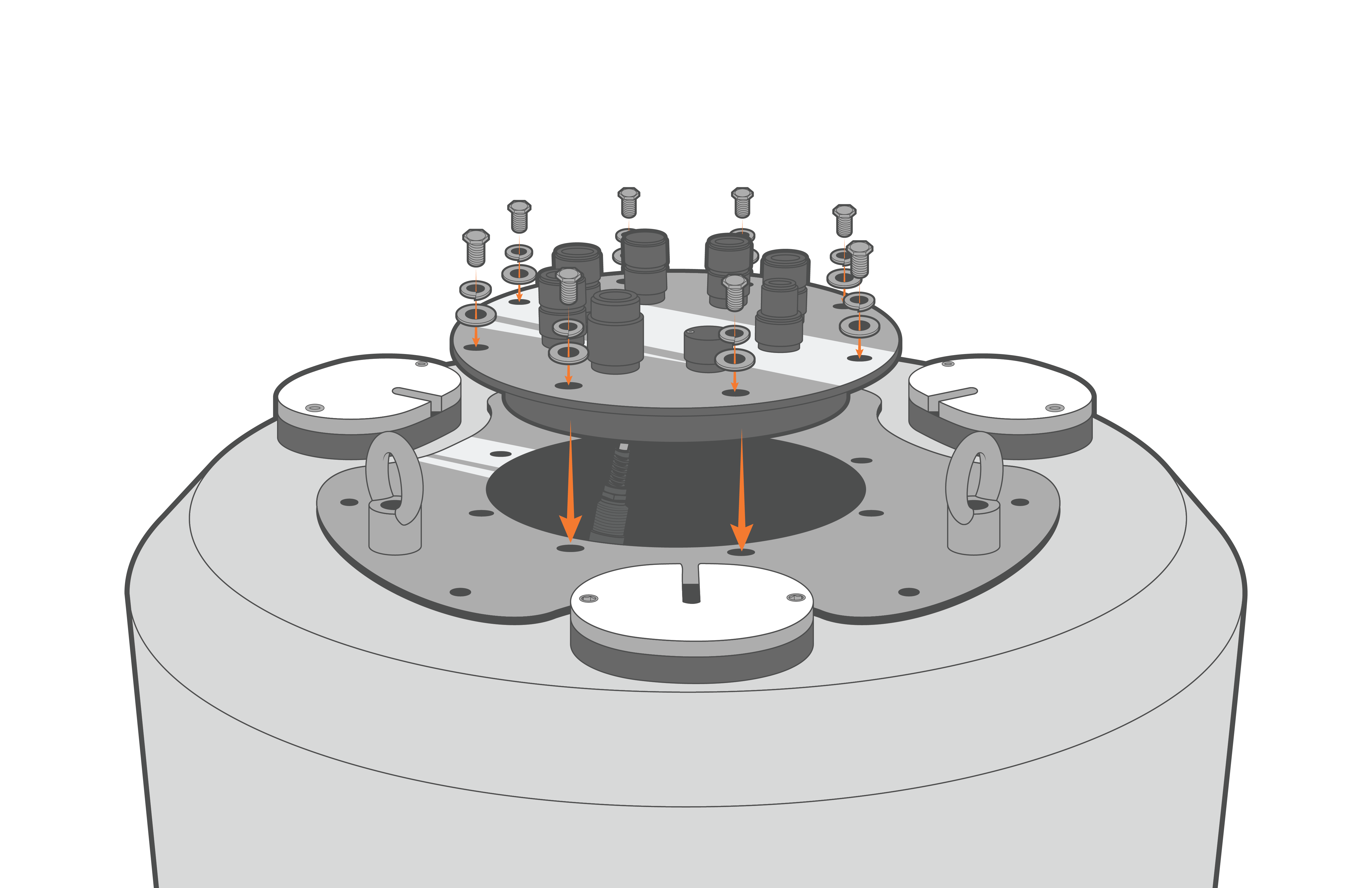
Figure 17: Bolt down the X2-CB/X2-CBMC. |
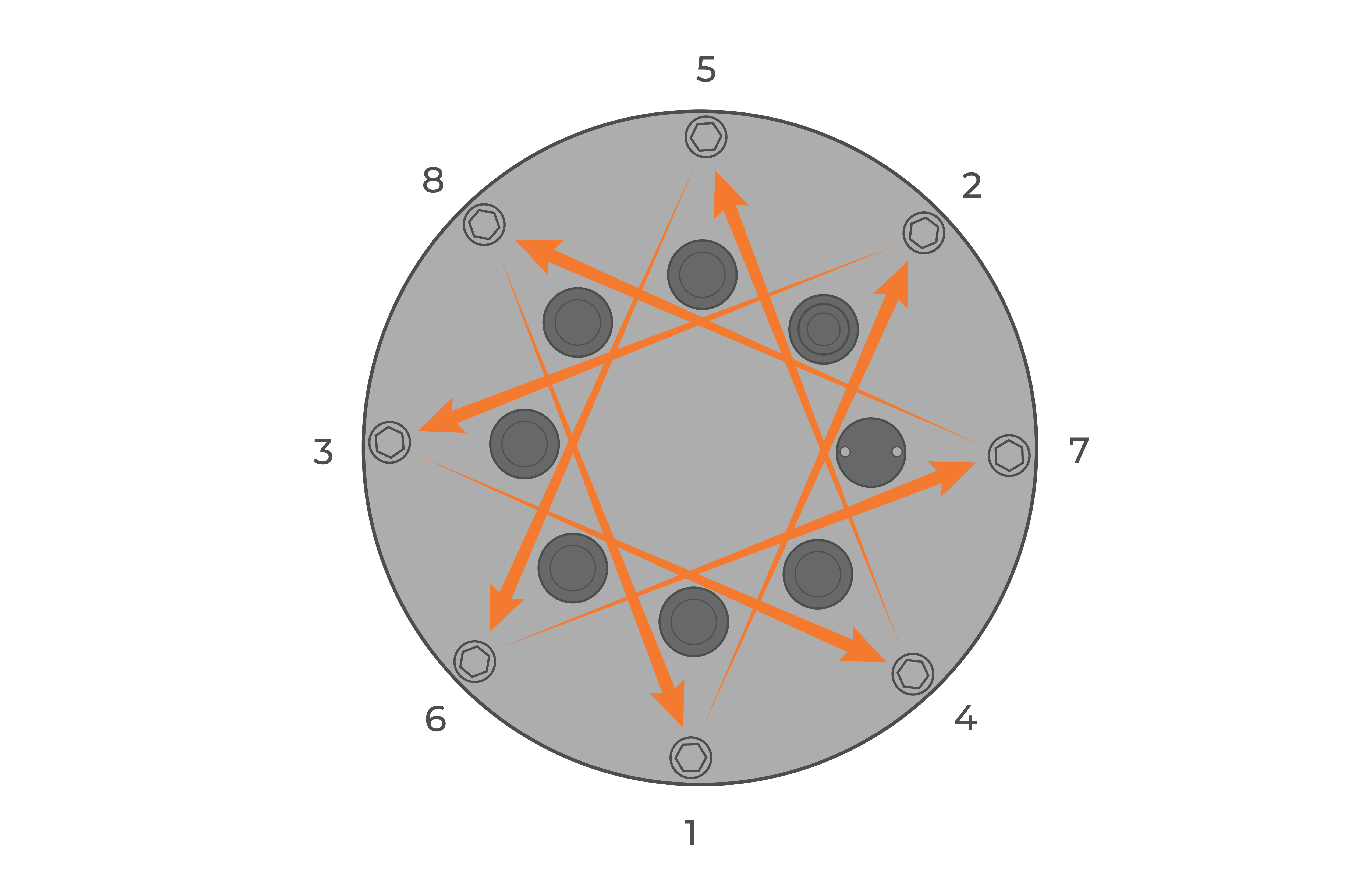
Figure 18: Bolt down the logger in a crisscross pattern. |