
Planning a Medium-Deep Water Mooring for Small Data Buoys
Note: NexSens Technology supplies mooring hardware to support user-designed systems but does not endorse any particular mooring strategy for any specific application and does not take responsibility for mooring performance or damage resulting from mooring failure.
Medium-Deep Water Deployment Considerations
While many medium-deep water (>100m depth up to approx. 1000m depth) monitoring projects require large buoy platforms due to sensor loads and corresponding power requirements, there may be some cases where a smaller buoy platform is desirable. This can facilitate measurements from a small package of power-efficient sensors where only near-surface (<50m) measurements are required and provide a solution that is easier to lift and handle by project personnel.
By small data buoys, we are generally referring to CB-Series buoys up to and including the CB-450 model. While these are small and light enough to lift manually by 1-2 persons depending on the model, a medium-deep water mooring system will generally have a sizable anchor weight. As such, a suitable vessel equipped with winch and crane is strongly recommended for lifting and controlled release of equipment to avoid injury to personnel or damage to equipment.
Mooring Configuration
Whereas two-point moorings with suspended sensor lines are often a viable option for shallower applications, medium-deep water moorings will typically be single-point due to the required mooring line length. This means that suspended sensors will be mounted along the primary mooring line, and special care must be taken in the design to ensure that twisting or stretching of data cables does not take place, as this can lead to failure even within a short timeframe.
Some general suggestions and points for consideration when planning this type of deployment are described in the following sections:
Mooring Line Length and Drift Radius
Chains for Controlled Movement vs. Ballast Weight
Mooring Line Length and Drift Radius
In order to determine the appropriate mooring line length, it is first necessary to have a fairly accurate water depth measurement at the deployment site and overview of the expected water level changes. In most applications, mooring line lengths should be ~50% greater than the median water depth to account for water level fluctuations.
The potential drift radius of the buoy, determined by the water depth and mooring line length, is important to calculate to understand if the mooring line will work for the application. The maximum drift radius can be theoretically calculated using Pythagorean theorem as illustrated in the diagram below and using the following formula:
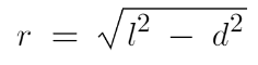
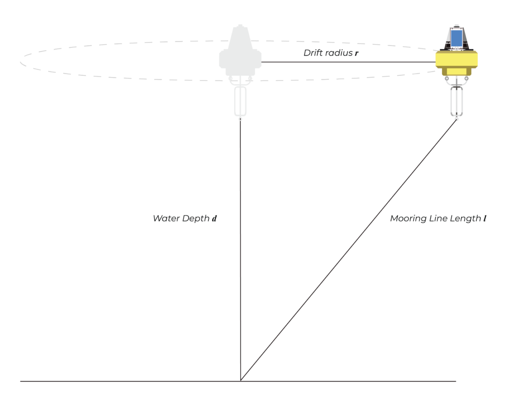
Figure 1: Determination of drift radius r
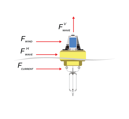
While this is only a theoretical calculation which may vary in an actual deployment, especially depending on the physical properties of the mooring line, it can serve as a basis for determining the total mooring line length (also see Mooring Hardware Materials). Too large of a drift radius may result in the buoy coming into conflict with the shore, infrastructure such as docks, or ship traffic. However, a mooring line that is too short can put the buoy at risk of submersion from horizontal loading during high wave and current conditions. The diagrams below illustrate this effect.
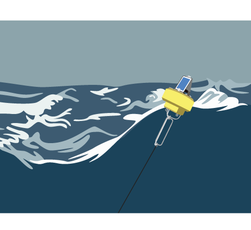
Figure 2: Depiction of horizontal loading resulting in buoy listing to one side. |
A general principle is that the buoy should be allowed to move somewhat freely with waves and currents rather than attempting to firmly hold it in place at an exact point. How much drift radius can be tolerated must first be determined, and then the total mooring line length can be calculated.
Chains for Controlled Movement vs. Ballast Weight
One strategy to provide an adequate potential mooring line length but provide some limitation on the buoy’s free movement is to use a heavy bottom chain as a part of the mooring system. The idea of the heavy bottom chain is that it can be lifted up from the seafloor as the buoy is pushed away from its centerline during rough conditions, yet provide enough resistance to dampen this effect.
However, the total buoyancy of the buoy must be carefully considered at this stage, as the chain cannot be too heavy such that it contributes to submersion of the buoy if it becomes fully drawn up from the seafloor. A method for slightly reducing the chain weight while simultaneously preventing it from becoming caught on objects on the seafloor is to install trawl floats at the terminus of the chain, at the location where the primary mooring line is connected. The buoyancy provided by these floats can help to maintain a segment of the chain in suspension as illustrated in Figure 4.
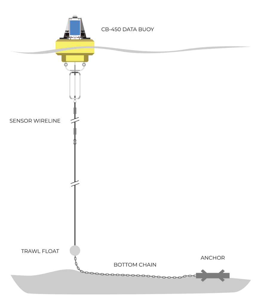
Figure 4: Mooring system overview with trawl float supporting bottom chain.
System Maintenance
A secondary consideration in calculation of mooring line length is serviceability of the instruments deployed. For practicality, it may be desirable to be able to access sensors mounted along the mooring line without having to lift the entire anchor system from its placement. This additionally helps to ensure that the buoy remains stationed at precisely the same location both before and after service.
Depending on sensor depths, this may or may not be achievable, but it will be theoretically possible any time the sensor depth is less than the drift radius, provided that maintenance is carried out under low and/or calm water conditions. Heavy chain connected to the anchor can also contribute to facilitating this, since it normally rests on the seafloor and contributes to anchor weight but may be lifted up during maintenance (preferably with the assistance of a winch or crane on the service vessel).
The diagram in the previous section illustrates an example where placement of the two sensors is less than the drift radius when accounting for the bottom chain length, so it should be possible to access the sensors for maintenance without disturbing the anchor placement.
Mooring Hardware Materials
Mooring Lines
A wide range of hardware options are available, and these can largely be selected based on site conditions, but there are a few critical points which should be considered.
Sensors suspended below the buoy frame can optionally be mounted onto NexSens-issued stainless steel mooring lines. Sensors can be securely mounted using MC-600 mooring clamps specifically designed for use with these mooring lines.
Buoyancy Control
Due to the weight of such wirelines, it is often preferable to use a neutral-buoyancy or even net positive buoyancy mooring rope with sufficient strength to perform well in the site conditions, for example Superdan® 8-strand or 12-strand ropes. Mooring lines with elastic properties may also help to reduce the total line length required and thereby reduce the drift radius as well.
If a positive buoyancy rope is used, this may result in some slack in the mooring line especially during calm conditions, thus forming a so-called S-shaped mooring as pictured in the diagram below. A potential issue with this is rope floating up and coming into contact with sensors, which can cause measurement interference, particularly on optical sensors. Rope floating all the way to near the surface can also present a risk of being snagged by passing boat/ship traffic. For those reasons, some weight should be added to limit the amount of flotation that can occur, similar to what is illustrated in the figure. However, it is important to keep in mind that this will count against the net buoyancy provided by the buoy.
Biofouling resulting in growth on mooring lines can also contribute additional weight during a deployment, so buoys and mooring lines should be periodically inspected and cleaned to ensure there are no issues. Any visual change to the way the buoy sits on the water surface during calm conditions (e.g. listing or sitting lower than normal) should immediately be inspected.
Figure 5: S-shaped mooring with weight applied to avoid mooring rope coming into contact with sensors.
Mooring Connections
To connect mooring components together, various shackle types may be used. Here, it is important to consider the materials of construction. The internal frame of CB-Series buoys is constructed of Type 316 stainless steel. Thus, to avoid mixing metals, any shackles connected directly to the buoy should also be made of 316 stainless steel.
At the seafloor, galvanized steel shackles, bottom chain and anchors may be used, provided there is consistency of materials. To guard against corrosion in saltwater environments, the buoy frame should be equipped with zinc anodes (NexSens part number CB-ZA).
Sensor Cable Protection
For protection of sensor data cables, it is recommended to secure the cable using steel-lined cable ties at many points along the sensor wireline (or equivalent mooring line). This is to ensure that there is plenty of slack in the data cable and that all loads are carried by the wireline/mooring line and NOT the data cable. Twisting in the wireline should be reduced as much as possible. This can, in some cases, be achieved by using a stainless steel swivel at the point where the wireline connects to the primarily buoy mooring line. A swivel should NOT be used directly at the connection to the buoy frame, as this will allow the buoy to rotate around the mooring line connection. An exception to this would be if no sensors are suspended below the depth of the buoy’s internal frame.
Deployment
Due to the size and total weight of medium-deep water moorings, it is strongly recommended to deploy using an appropriately-sized vessel equipped with a crane and winch for controlled lifting and release of the mooring system and buoy. The following describes the process for a typical deployment.
- Lay out the buoy and mooring hardware on the vessel’s deck such that all connections can be made and the mooring line can be paid out without risk of tangling.
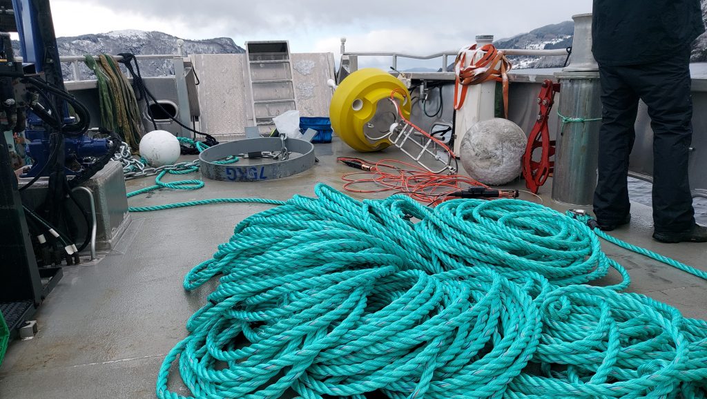
Figure 6: Buoy mooring hardware carefully arranged on deck to avoid tangling.
- Use the crane to lift the heavy anchor and carefully lower it over the side of the vessel at the deployment site. Use the winch to hold the mooring rope such that the release is controlled throughout.
- Tip: To pay out the anchor and bottom chain without having to run the chain through the winch, an off-load hook (e.g. from Henriksen or equivalent) is a handy helping device. Commonly used with lifeboats, these hooks have an automatic self-open function that causes the hook to release when the load is released. Using the winch to support the rope connected to the chain, lower the anchor into the water deep enough that the anchor load begins to be carried by the chain connected to the winch-supported rope rather than the crane, and the anchor will be released in a very controlled manner.

Figure 7: Anchor supported by off-load hook. |
Figure 8: Anchor being lowered into water with crane. |
- After drawing the wire of the crane back to its original parked position, begin slowly paying out the mooring line using the winch. Before the anchor touches the seafloor, there is the possibility to make fine adjustments to the mooring location by carefully navigating the vessel, being sure to avoid tangling of the mooring line with the motor.
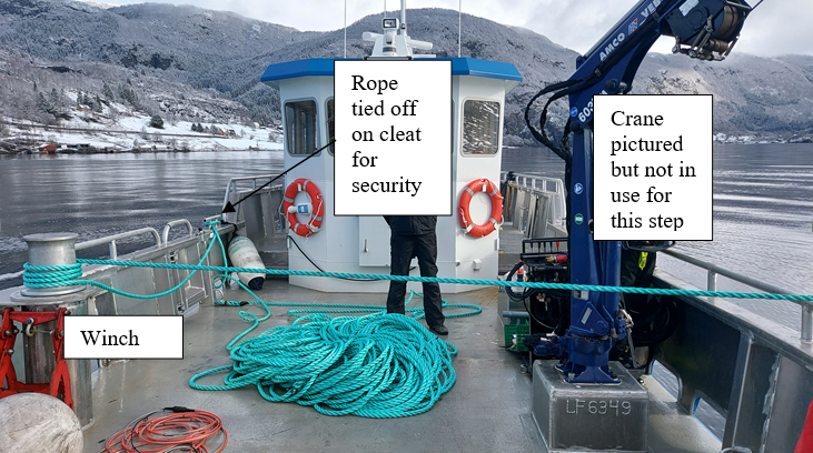
Figure 9: Paying out the mooring line using the winch.
- Once the entirety of the mooring line is paid out, be sure to double check all sensor connections and that the buoy and LED beacon are powered up. Then, carefully place the buoy in the water. This can either be done by lifting it and placing it with the crane and off-load hook as with the anchor, or by placing it into the water through a bow gate if the vessel is equipped with one.
Once deployed, observe the buoy’s movement to ensure it appears to be stable. If the buoy is equipped with a GPS device, track the coordinates for a few days to ensure it is staying within the desired drift radius, and consider configuring a geofence alarm to provide notice if the buoy moves outside the desired boundaries.