
Large Platform Data Buoys User Guide
NexSens CB-650, 950, 1250 Data Buoys
NexSens large platform data buoys are ideal for environmental monitoring in lakes, rivers, harbors, estuaries, and coastal and ocean waters. The buoys differ in buoyancy, freeboard, solar capacity and pass-through port size. Otherwise, they are constructed with the same materials and methods.
Measurement System Verification
1. It is best to configure and test electronics on a lab bench prior to installation on the buoy.
2. When purchased with NexSens X-Series data loggers, refer to the following knowledge base articles for setup and integration:
NexSens X3: https://www.nexsens.com/knowledge-base-v2?cat=data-loggers&prod=x3
WQData Live: https://www.nexsens.com/knowledge-base-v2?cat=software&prod=wqdata-live
3. When the measurement system is fully functional, move on to the buoy assembly.
Buoy Assembly
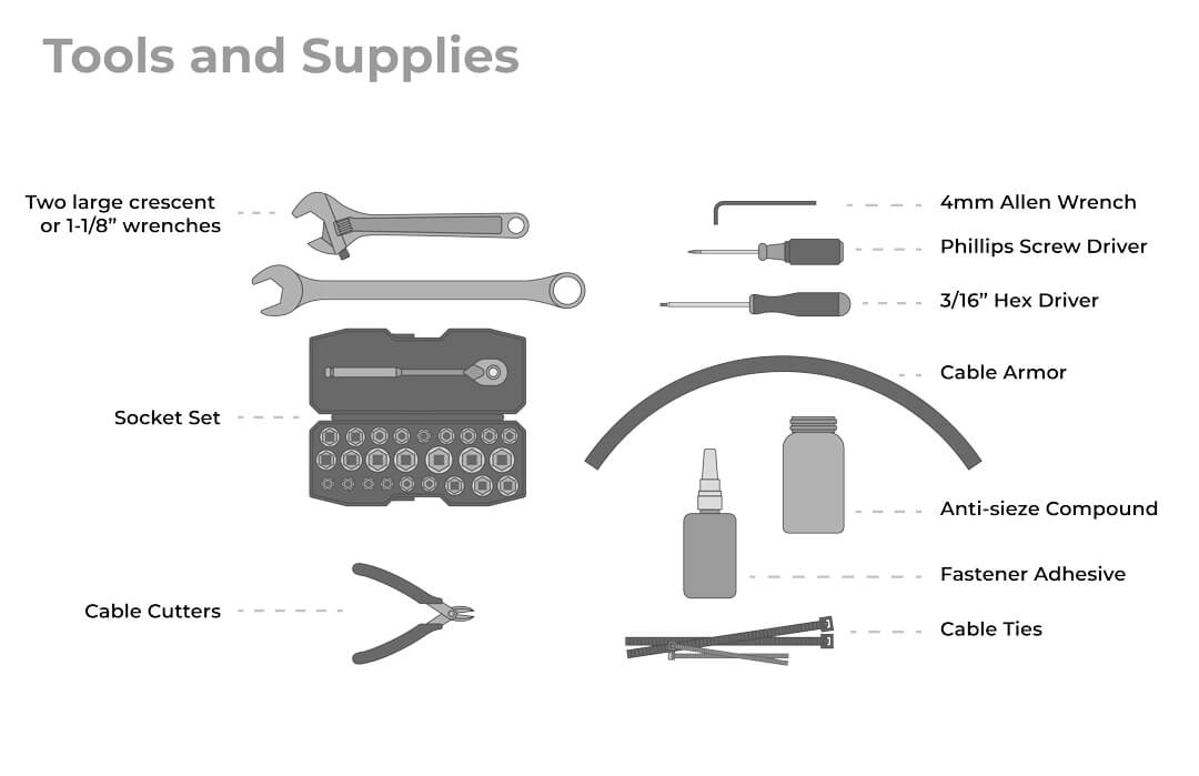
Only basic hand tools and a few supplies are needed for assembly. Cable ties and a thread lock adhesive will ensure the buoy can perform well in rough waters.
Solar Panel Removal
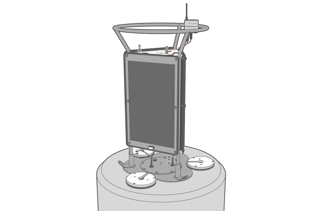
4. Before attaching the solar tower to the buoy hull, it’s best to handle top-side equipment mounting and cable routing. Remove the solar panel with the lone cable.
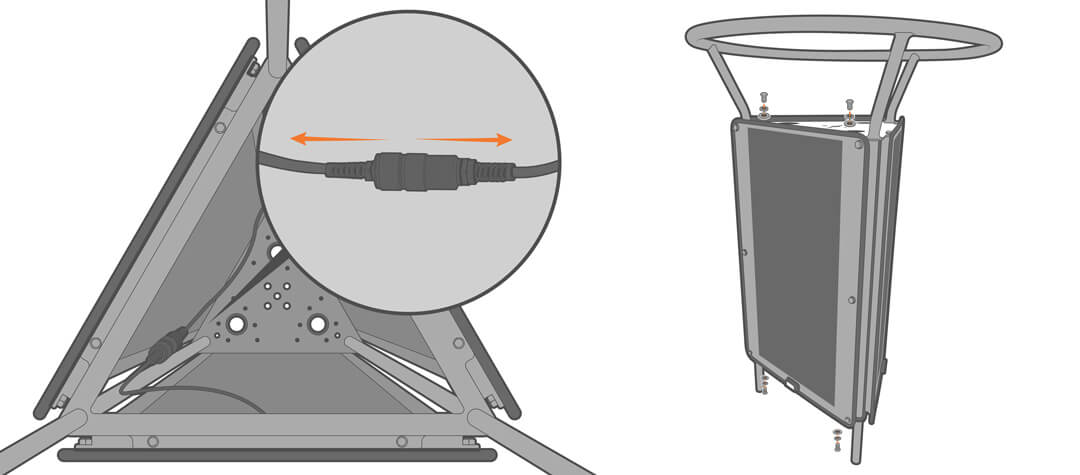
5. Mount any top-side sensors with the panel removed and secure all excess cable behind the solar panels with cable ties.
- For sensor-specific mounting, refer to the appropriate documents in the Knowledge Base.
- Connector guidelines can be found in the Maintenance section under Clean and Inspect Installed Sensors and Cables.
Deployment Pipe
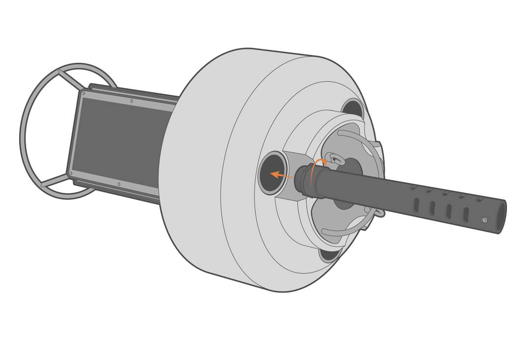
For subsurface instrument deployments, the NexSens Buoy Deployment Pipe Assemblies can be used to protect sensors and make maintenance easy.
6. Screw the threaded end of the deployment pipe into the bottom of the desired pass-through port.
M650 Solar Marine Light
7. Refer to the manufacturer’s guidelines to set up and activate the beacon before installation.
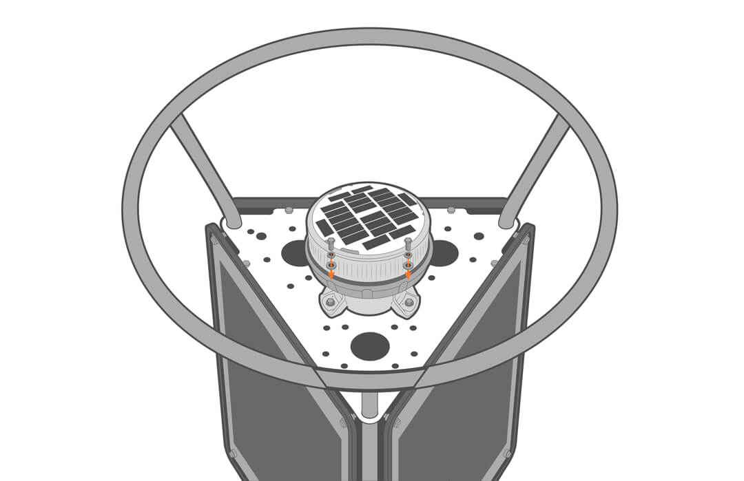
8. Attach the M650 Beacon to the center of the solar tower top plate using the included mounting hardware.
NexSens Data Logger
9. Place the included black isolation washers on the mount. Be sure to note the location of each port as the numbers will not be visible once mounted.
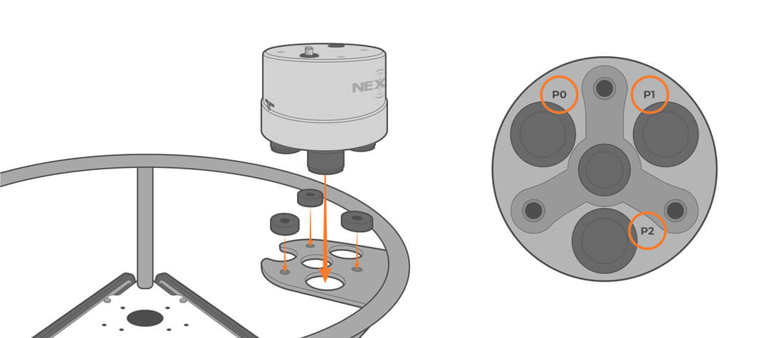
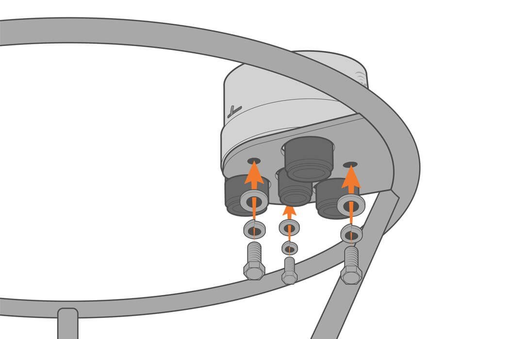
10. Secure the logger in place using the included hardware.
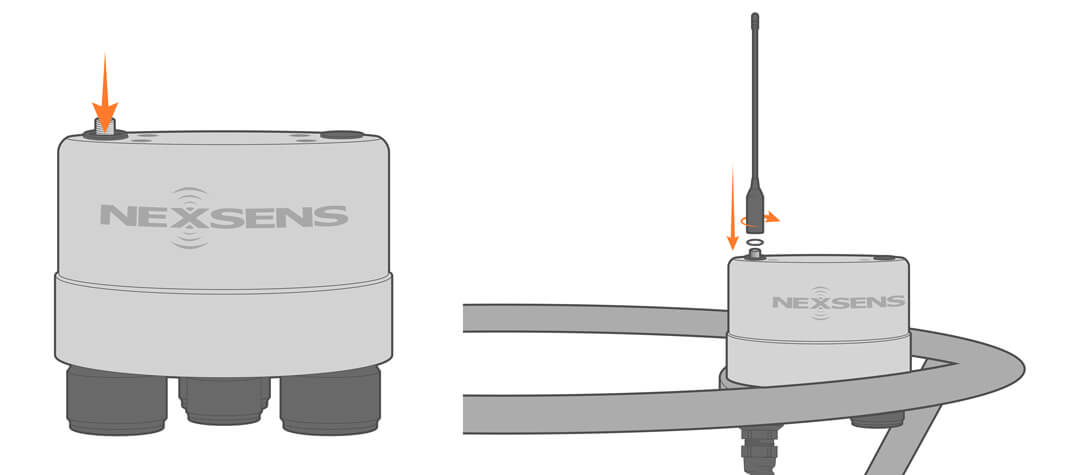
11. Install the selected telemetry antennae, ensuring that the o-ring seal is in place.
Attaching the Solar Tower and Buoy Hull
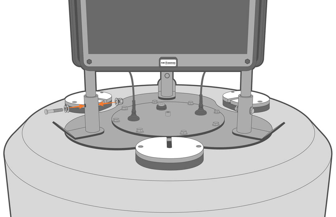
12. Using the appropriate lifting gear, raise and place the solar tower into the tower hubs.
13. Install the bolts with nylon-insert lock nuts through the hubs to secure the tower in place.
14. Plug the solar panel power into the battery well lid cable, and then run the battery power cable to the logger, but do not plug it in yet.
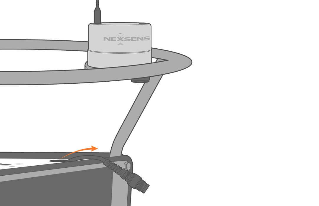
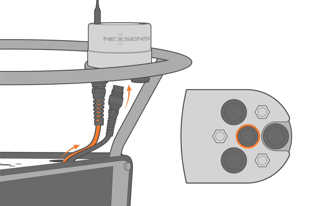
15. Route the sensor cables up through the solar tower to the data logger and connect to the pre-determined port.
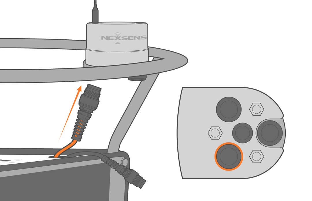
16. Power the logger by connecting the power cable to the center port.
17. Before moving on, confirm all cables are held in place with cable ties to prevent chaffing and damage over time.
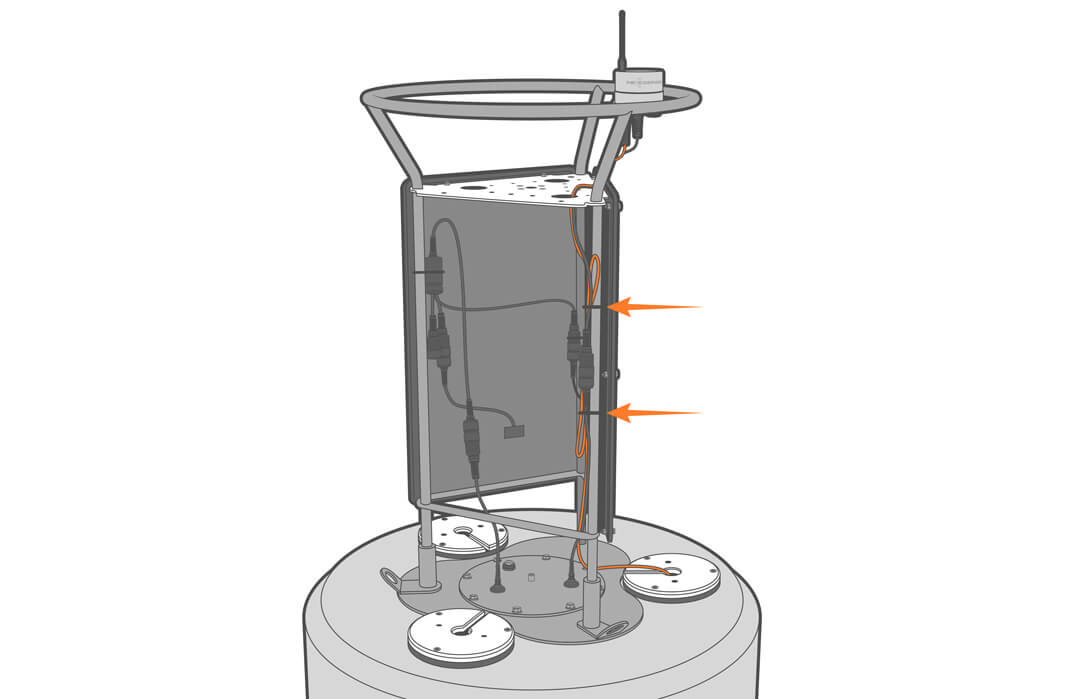
18. Reattach the solar panel.
Instrument Cage and Anti-Rotation Collar
19. Using the appropriate lifting gear, lower the buoy onto its side, being careful not to damage any top-mounted equipment.
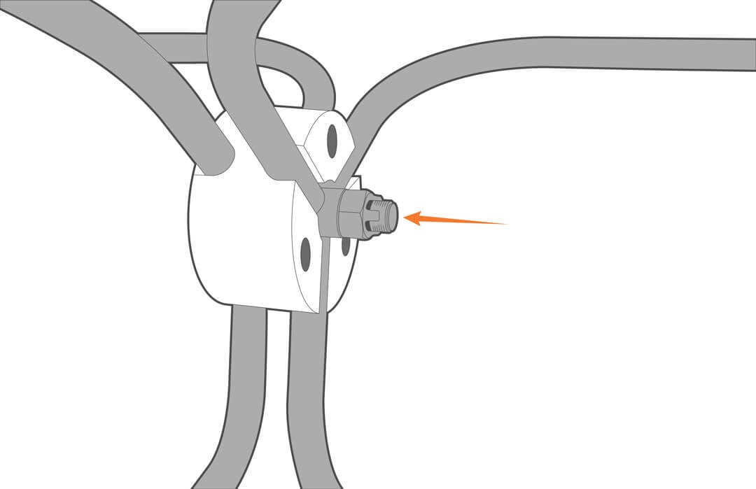
20. Place the anti-rotation collar between the instrument cage and the buoy frame, and run the bolt with the pinhole downward through the buoy frame into the cage.
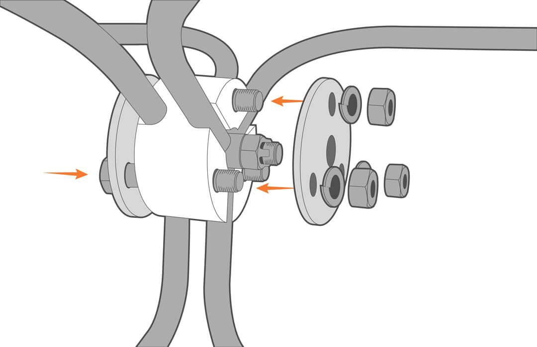
21. Align the two end plates and secure them using the supplied hardware.
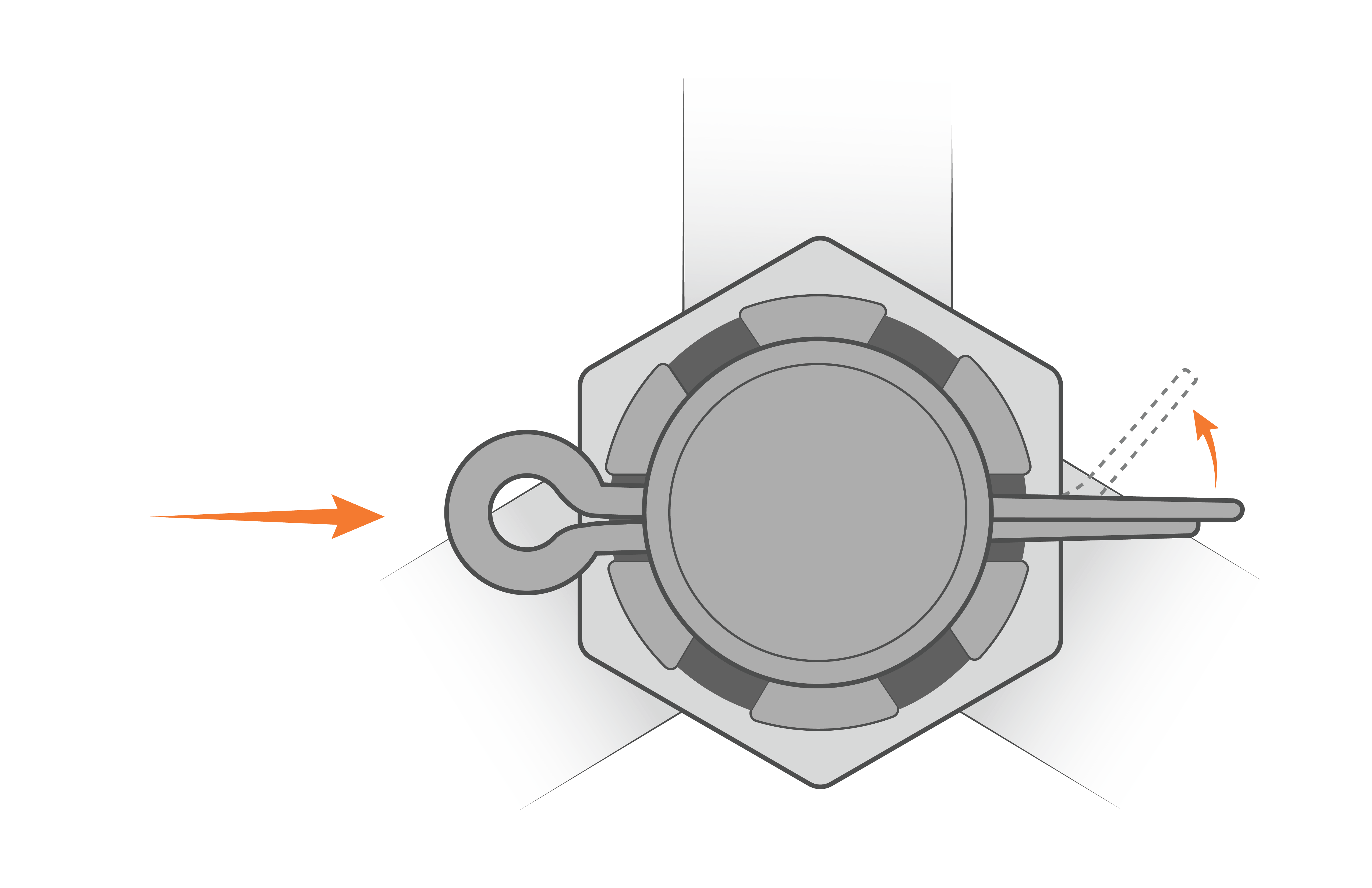
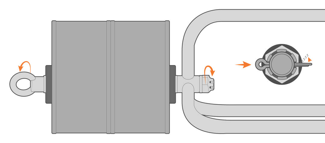
22. Secure the anti-rotation collar in place using the cotter pin and bend the long leg around one of the ridges on the castle nut.
Zinc Anode
Zinc anodes are only necessary in saltwater applications and must be purchased separately. Skip to the next section if your system does not include a zinc anode.
23. Remove the two screws from the anode.
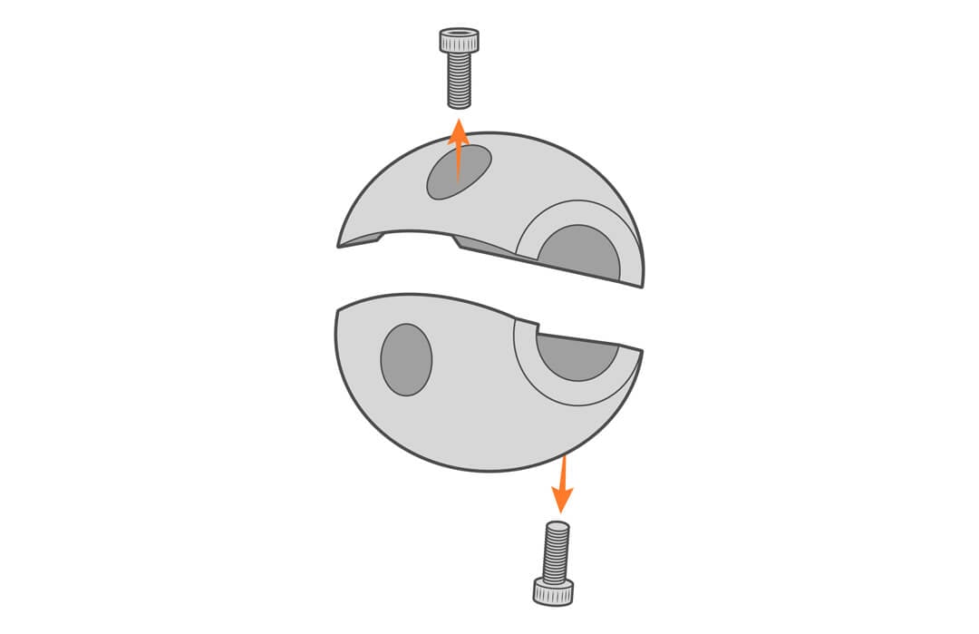
24. Mount an anode to the instrument cage leg and a second anode to the buoy frame.

Ballast Weight
All large platform buoys require ballast weight for stability. This can be accomplished with a heavy chain shackled to the bottom of the cage or with NexSens steel ballast weights. The amount of weight is dependent on local conditions, but a minimum weight for each platform is recommended.
| Buoy Platform | Minimum Ballast |
|---|---|
| CB-650 | 50 lbs |
| CB-950 | 100 lbs |
| CB-1250 | 150 lbs |
25. Remove the cotter pin, castle nut and lock-washer and insert the threaded rod assembly through the instrument cage.
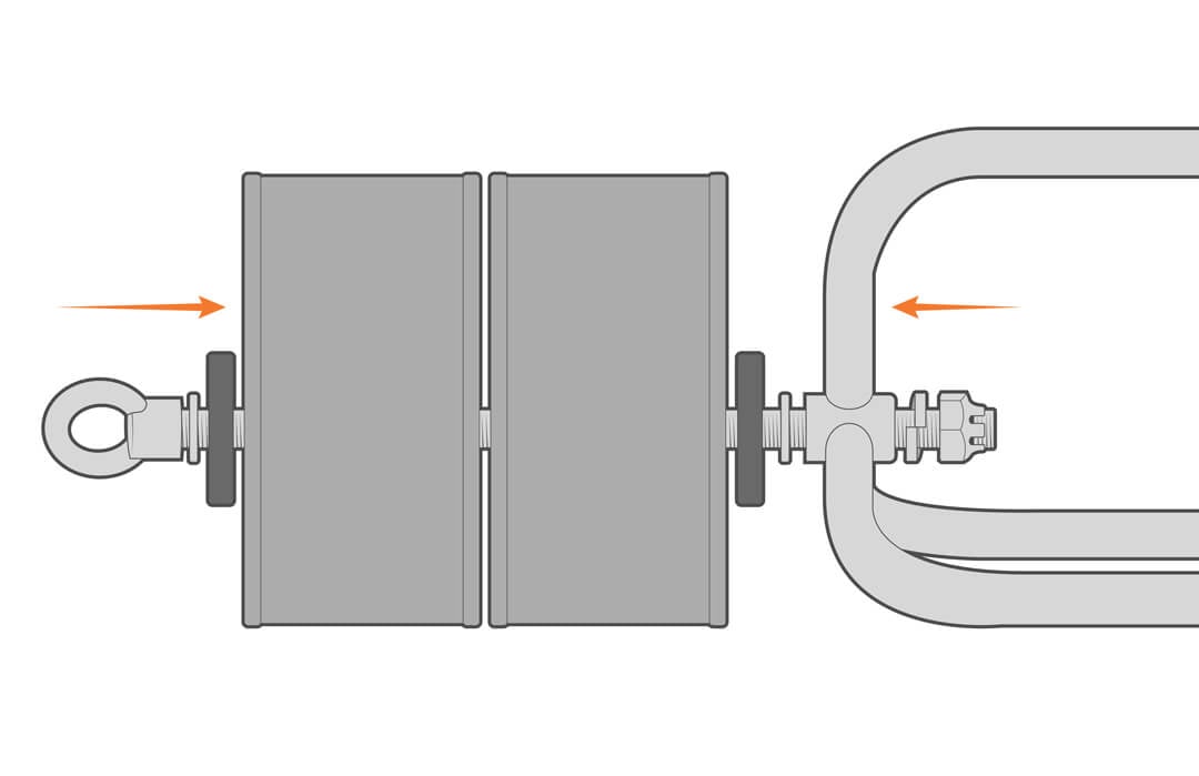
26. Secure the ballast in place with the previously removed hardware and cotter pin.
Deployment and Mooring Notes
Visit the links below for mooring and deployment tips.
Maintenance
As a general practice, measurement data, battery voltage, and other diagnostics (humidity, telemetry signal strength, etc.) should be monitored daily. Alert notifications for data and system functions can be used to detect anomalies and provide early warning that maintenance is required
Barring damage from extreme sea state, NexSens large platform buoys provide months of maintenance-free service when properly assembled and rigged. Most freshwater deployments should provide a full season of trouble-free performance, while saltwater-deployed systems may need to be periodically inspected for marine growth and damage from severe weather events.
Sensors and electronics may require more frequent maintenance and calibration; refer to the manufacturer’s recommendations.
Inspect the Vent
The vent releases pressure that may build up inside the battery well. This can occur from temperature changes and battery off-gassing. It is factory set for a 5 PSI differential pressure, but obstruction of the vent can lead to a gas buildup.
1. Clean the outside of the vent and do not allow debris or animal droppings to accumulate.
| WARNING: Sealed lead-acid batteries can be dangerous if they off-gas, producing hydrogen and oxygen, which are explosive. Under normal charging, the batteries emit very little gas, but a system malfunction could lead to overheating and off-gassing. An overheated or off-gassing battery should be replaced immediately.
Always vent the battery well by ensuring the vent is not obstructed and remove the lid manually (without power tools), allowing any trapped gases to escape. Never grind, cut, drill or use any flame on or near the battery well. |
2. If needed, order a vent replacement and follow the procedure in the repair manual.
Battery Maintenance
The buoys are powered by solar-charged, 12VDC sealed lead-acid (SLA) batteries with a typical life of 3 to 5 years. To prolong the battery life, keep the battery voltage above 11.5VDC. When the battery performance degrades, charge or replace the batteries.
1. Regularly check the battery voltage. If paired with a NexSens logger, battery voltage can be viewed on WQData LIVE.
2. When solar energy is unavailable (winter storage), consider disconnecting the batteries or charging them using the CB-Series battery float charger.
3. Visually inspect batteries annually for signs of corrosion, loose connections, or physical damage. Addressing these issues promptly can prevent more significant problems in the future.
- If the terminals are showing signs of corrosion, clean connections with a baking soda and water solution.
- Ensure that the mounting hardware is secure, and refer to the repair manual if needed.
4. If the batteries continue to drop below 11.5V, they should be replaced by a qualified technician with experience in low-voltage, high-current systems. See the repair manual for parts and procedures.
Desiccant Replacement
Desiccant is used to absorb the humidity and should be replaced annually or anytime the well is opened.
1. Remove the battery well lid.
2. Replace the desiccant.
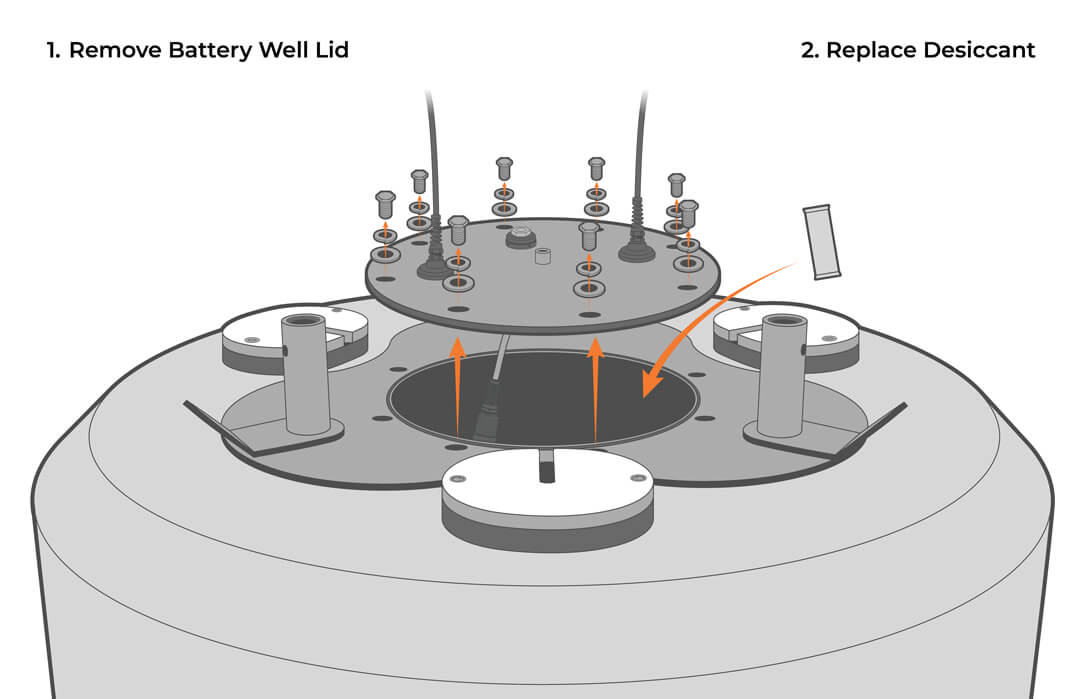
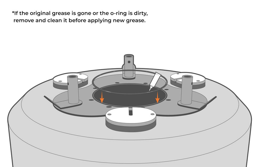
3. Check that the o-ring is clean and undamaged, and reinstall the lid, being careful to avoid trapping the cable under the lid. If the o-ring lubricant is no longer in place, apply a thin film.
Clean and Inspect the Solar Tower
1. Before cleaning the solar tower, be sure all sensors and power cables are connected or covered with a waterproof cap or tape.
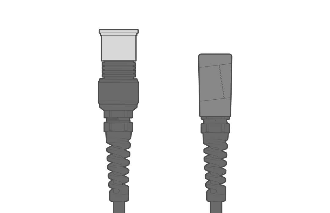
2. Clean the solar tower and panels of debris and animal/bird droppings using dish detergent and a soft cloth. A brush can be used on parts of the solar tower, but not on the panels.
*Note* Be careful not to use aggressive cleaning techniques or high-pressure water on the solar panel face. The outer layer is a thin polymer film that can be damaged.
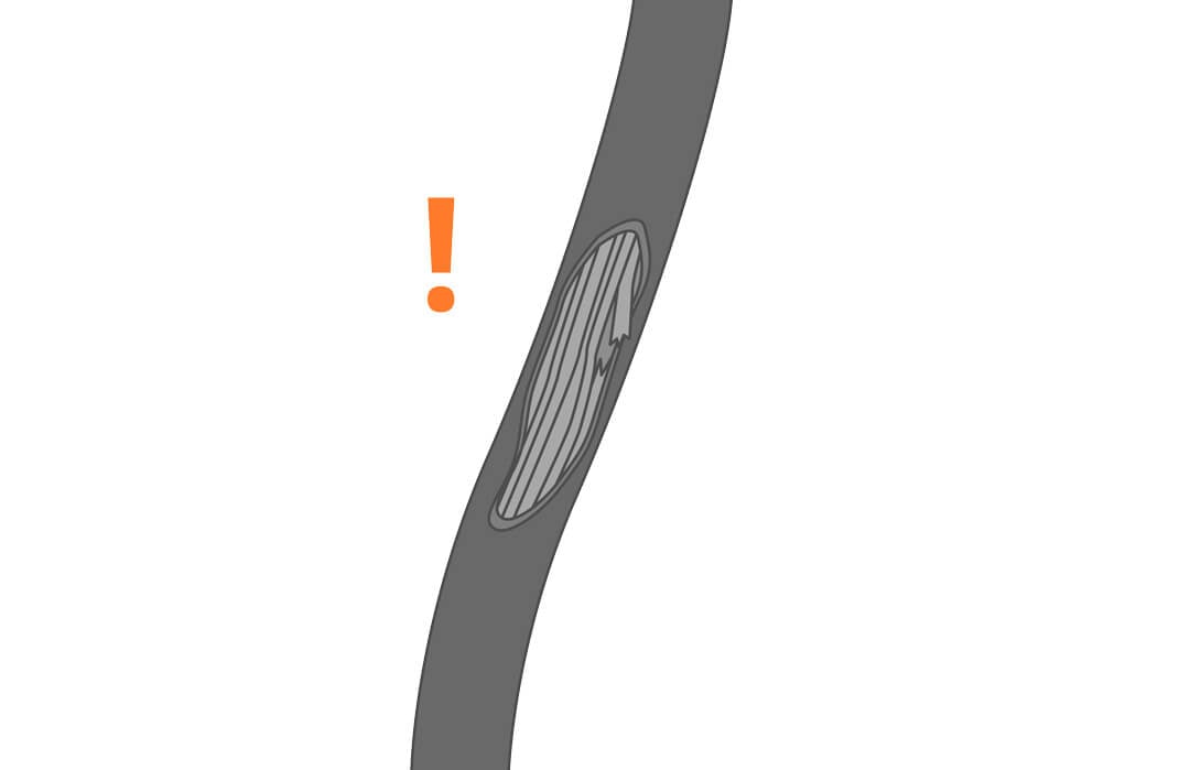
3. Inspect the tower and topside equipment for damage. Look for abrasions and any green (copper oxide) corrosion inside the thin outer film of the solar panels. This is a sign that the panel was damaged, and it should be replaced. See the repair manual for parts and procedures.
Clean and Inspect Installed Sensors and Cables
1. Unplug solar charging and power to all electronics.
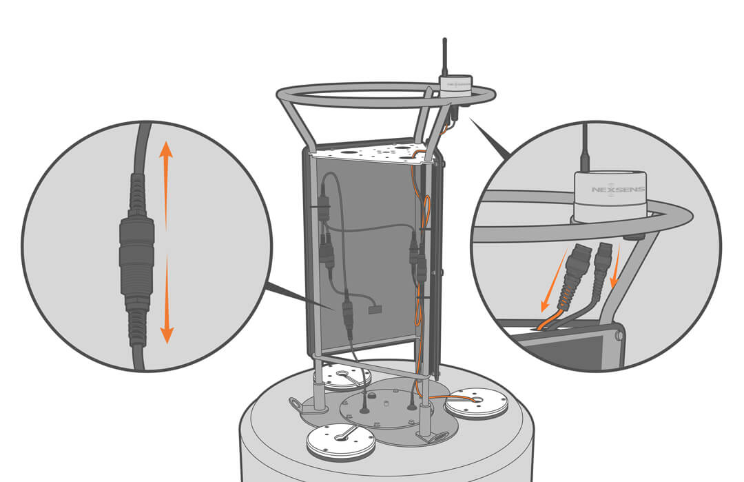
2. Clean and inspect any topside and submersible sensors and cables.
3. Test and recalibrate following the manufacturer’s recommendations.
4. Remove trapped moisture and particulates with compressed air.
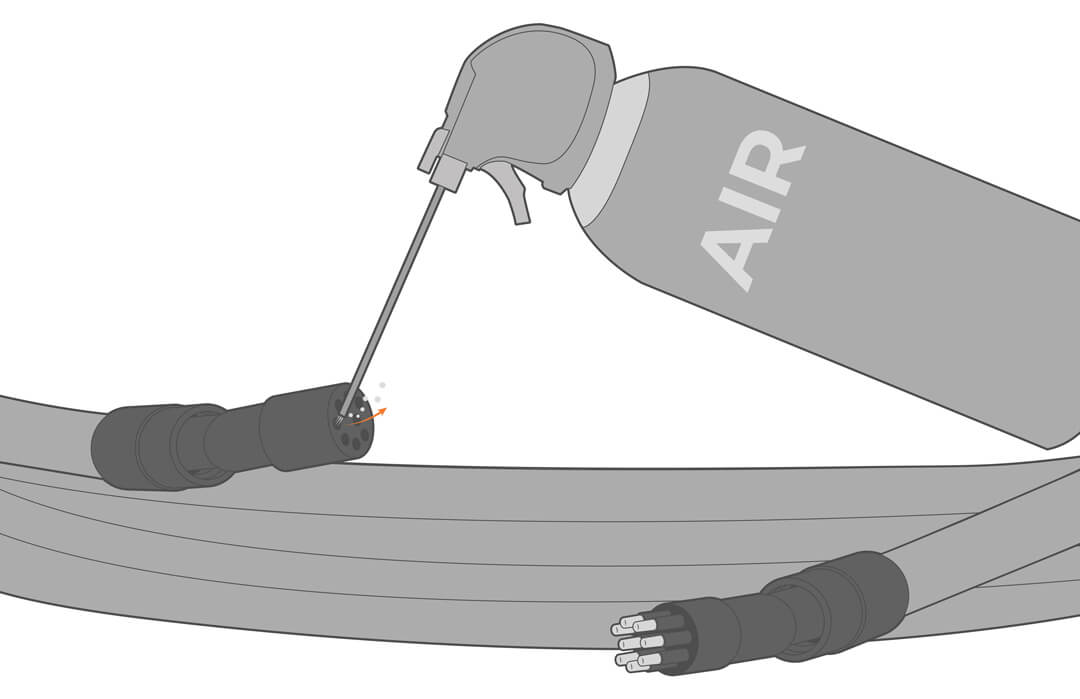
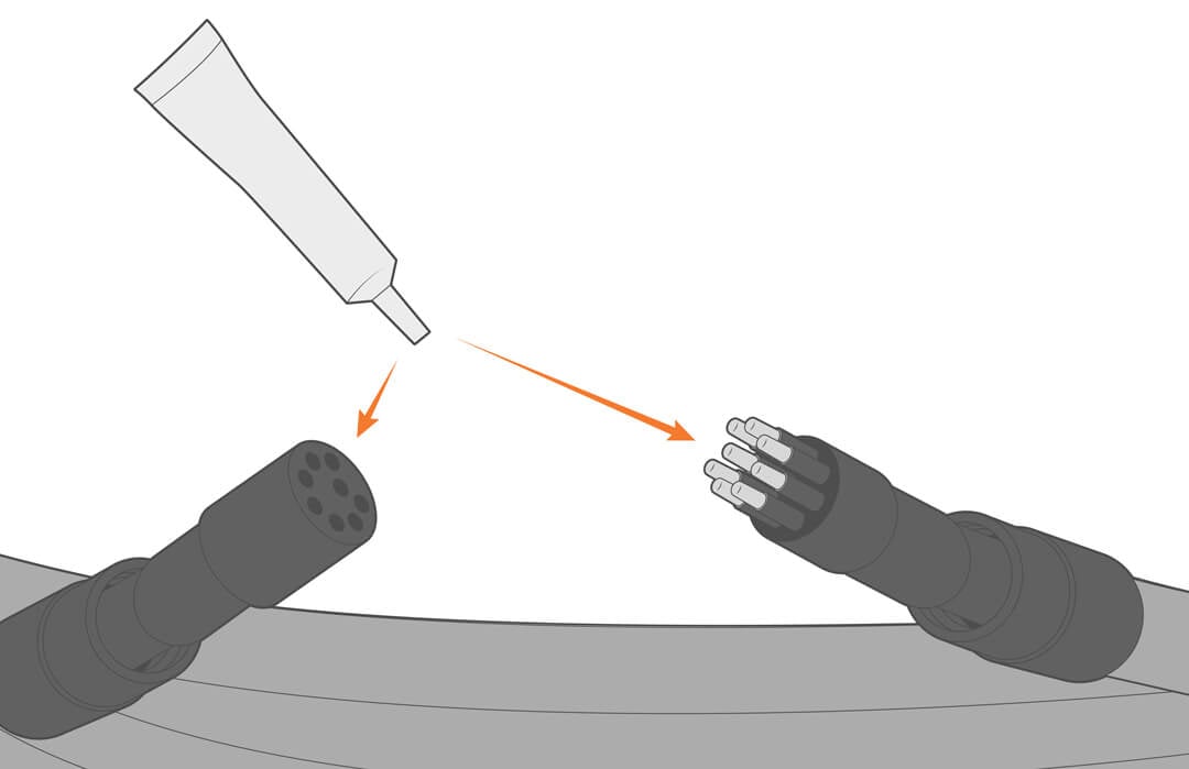
5. Before reconnecting, apply a thin film of silicone grease.
Cleaning the Buoy
The buoy should be cleaned at least annually, more often if needed. Marine growth can accumulate and weigh the buoy down, reducing the amount of buoyancy and freeboard.
1. Pull the buoy from the water and pressure wash all bottom-side components, including the hull, frame, cage, ballast, mooring lines, chains, hardware, sensors, and electrical cables.
2. It is recommended to coat below the waterline with an anti-foulant boat hull paint.
Anode Replacement
If the buoy is deployed in salt or brackish water, regular zinc anode maintenance is essential. Without it, stainless components starting at weld joints and crevices will corrode until failure.
1. Regularly inspect the anodes and replace annually or as needed.
- Replacement part number CB-ZA.
2. Remove the old anodes and follow the Zinc Anode instructions in the Buoy Assembly section for replacement.
Final Inspection – Subsurface Components
1. Before moving on, inspect all electrical and mooring lines and connections. Look for cable chafing, worn components (such as shackles, thimbles, wire rope, anchor connection, crimps, cotter pins, cinching wire or ties, etc.). Repair and replace as needed.
Storage
1. Before putting the buoy in storage, follow the cleaning and maintenance steps and the manufacturer’s recommendations for sensors and electronics storage.
2. To ensure the batteries are not drained over time, disconnect the power and solar cables from the battery well. Alternatively, use the CB-Series battery float charger to keep the batteries charged.
Troubleshooting
See the repair manual for troubleshooting and replacement procedures. Data logging and sensor troubleshooting can be found in the knowledge base.
| Error or Problem | Potential Causes | Solutions |
|---|---|---|
| Insufficient power – short battery life | Batteries beyond useful life (3 to 5 years) | Replace batteries |
| Elevated power consumption | Select sensors with lower power needs | |
| Insufficient power – solar panel failure | Debris or animal droppings partially covering solar panels | Clean the panels and watch for improvement in the battery voltage data for a few days. |
| Solar panel failure | Replace the solar panel | |
| Insufficient power – failed solar regulator | Voltage surge damaged the regulator | Replace the regulator |
| Breached buoy hull | Collision or impact | Repair or replace the buoy hull |
Checking Battery Voltage
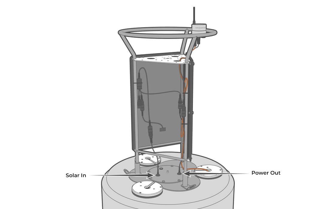
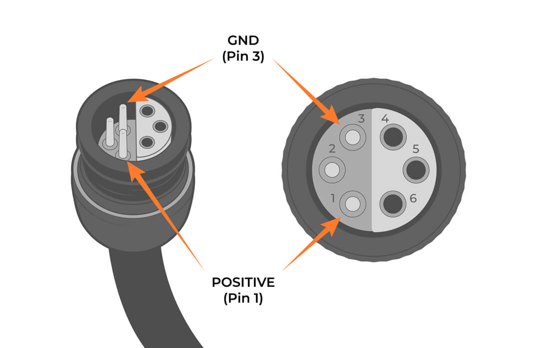
Check the output voltage of the battery by measuring between Pins 1 and 3 of the assembly’s UW-6 plug connector coming from the POWER OUT cable on the battery well lid. Test the voltage both in and out of direct sunlight to fully assess the functionality of the solar tower.
Healthy operational voltages range from 12-15V. The voltage depends on the amount of direct sunlight and the age/health of the installed battery.
NexSens Warranty
View the NexSens Warranty.
NexSens Service Request
To return equipment for evaluation and repair, visit this page for more information.