
CB-25-SVS Wave Buoy Overview
The CB-25-SVS Wave Buoy is a simple, compact platform that integrates the NexSens X2-SVS Wave Data Logger and the SeaView Systems SVS-603HRi wave sensor for both water and atmospheric observations. The SVS-603HRi sensor offers accurate measurements of wave height, period, direction, and more. Two additional sensor ports on the X2-SVS allow for further real-time observations of atmospheric and water quality data with a host of environmental sensors. The buoy features (3) 1.5″ sensor pass-through ports, an integrated solar tower with (3) 4-watt solar panels, and a topside plate supporting a solar marine light, weather stations, and other environmental sensors. An optional EXO-S cage supports the YSI EXOs series of water quality sondes.

Figure 1: CB-25 |
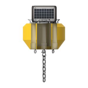
Figure 2: Internal X2-SVS and pass-through view. |
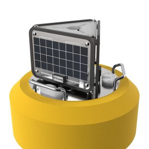
Figure 3: Top-side plate and solar tower view. |
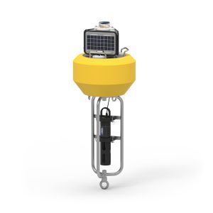
Figure 4: CB-25 |
Key Buoy Components and Definitions
Buoy Hull – Constructed of cross-linked polyethylene foam with a durable polymer outer layer and stainless steel plates on the top and bottom of the buoy providing a net buoyancy of 25 lb (11.34 kg).
Stainless Steel Plates – The top-side stainless steel plate provides (3) lifting handles, and the bottom-side stainless steel plate provides (4) 3/8″ eye nuts supporting drifting, tethering, and mooring applications.
Key Specifications
The key specifications of the CB-25-SVS buoy are given below:
- Hull Outer Diameter: 18” (45.72cm)
- Hull Height: 11” (27.94cm)
- Center Hole Inner Diameter: 5.5” (13.97cm)
- Center Hole Height: 11″ (27.94cm)
- Pass-Through Hole Diameter: 1.5″ (3.81cm)
- Tower Height: 8” (20.32cm)
- Solar Panels: 3x 4-watts
- Weight: 30 lb (13.61kg)
- Net Buoyancy: 25 lb (11.34kg)
- Hull Material: Cross-linked polyethylene foam with polyurea coating & stainless steel deck
- Hardware Material: 316 stainless steel
- Mooring Attachments: 4x 3/8” eye nuts
SVS-603HRi Wave Sensor Specifications
The SVS-603HRi wave sensor comes with a pre-determined list of parameters described below. The X2 data logger includes a pre-loaded SVS-603HRi script that can recognize the parameters and communicate with the sensor via RS232 communication on its internal P2 port.
| Parameter | Unit | Description* |
| Hs Wave Height (Significant wave height) | Meters | Average of the highest one-third of all wave heights during the 20-minute sampling period. |
| TP (DPD) Wave Period | Seconds | Period calculated with the maximum wave energy. |
| Dominant Wave Direction | Degrees | Dominant wave direction during the sampling period. (Degrees from N). |
| Mean Wave Direction (MWD) | Degrees | Energy averaged wave direction based on energy from all waves over the entire spectrum (Degrees from N). |
| Te Energy Period | Seconds | Energy weighted average period across the energy spectrum. |
| Noise Coeff GN** | — | Noise model coefficient. Used for troubleshooting purposes by SeaView. Expected range: < 20 |
| Diag Parm 1** | — | Internal diagnostic parameter 1. Used for troubleshooting purposes by SeaView. Expected range: > -0.35 |
| Diag Parm 2** | — | Internal diagnostic parameter 2. Used for troubleshooting purposes by SeaView. Expected range: < 2 |
| RMS tilt angle | — | Root mean square calculation of the tilt angles measured by the sensor in a sampling cycle. |
| Max tilt angle | — | Maximum tilt angle measured by the sensor in a sampling cycle. |
| Identity | — | Unique identifier set by the user. Must be an integer if it is to be recognized by the X2 data logger. |
| Date | yymmdd | — |
| UTC Time | hhmmss | — |
| Sample Number (Index) | — | Current sample number between 0-2047. Sample number will start from 0 again on the 2048th sample. |
*The SVS-603HRi parameters follows the NOAA Standard for Meteorological Data. More information can be found at the NOAA National Data Buoy Center (NDBC).
**In the event of mooring constraints, current or wind based motion anomalies, and other non-idealities, one or more of these parameters will generally spike out of the expected ranges.
Battery Life
To preserve battery life, the SVS-603HRi sensor will be powered only for the duration of its internal sampling period. By default, the wave sensor uses the NDBC standard 20-minute sampling period, covering 2048 samples at a frequency of 1.7244 Hz. However, if other sensors are connected to the X2-SVS Wave Data logger, the sampling period may need to be reduced to increase deployment longevity. SeaView Systems has confirmed through real-world deployment and analysis that a sampling period as low as 5 minutes will still provide accurate and comparable data to the standard 20-minute sampling period. Thus, if required, NexSens can make this adjustment based on battery life calculations.
Note: If the SVS-603HRi is set at the default ~1.72 Hz rate to complete 2048 samples in 19.794 minutes, it is recommended to set the log and sample interval for the wave sensor to 20 minutes or greater on the X2. Otherwise, data will be repeated as the summary data will remain on the wave sensor until another 2048 sample set is complete. The log and sample interval must always be greater than the sample rate for the wave sensor.