
Nortek Signature Current Profiler X2 Integration Guide
The Nortek Signature Series sensor is a high-performance acoustic doppler current profiler (ADCPs) used for measuring wave current velocity (via multiple cells), current direction, water temperature, and pressure.
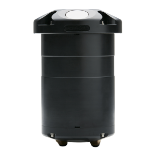
Figure 1: Nortek Signature Series ADCP.
Configure Deployment Template
Nortek’s Signature Deployment software must be used to configure a Signature Series sensor for use with an X2 Data Logger.
- Download and install the Signature Deployment software from Nortek.

Figure 2: Launch the Signature Deployment software.
- Connect the Nortek-supplied instrument Ethernet communications cable to a network switch on the PC (or to any available switch on the shared local network) and supply power through the barrel power connector splitter.
- Navigate to Communication|Connect to Instrument.
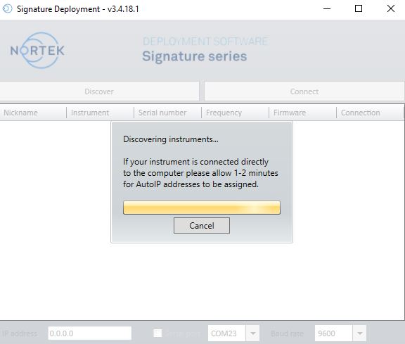
Figure 3: Network discovery of Signature instrument.
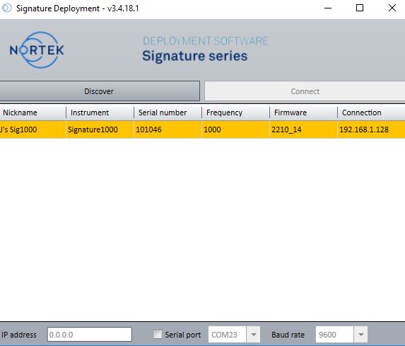
Figure 4: Instrument found.
- Left click to highlight the Signature and then select Connect.
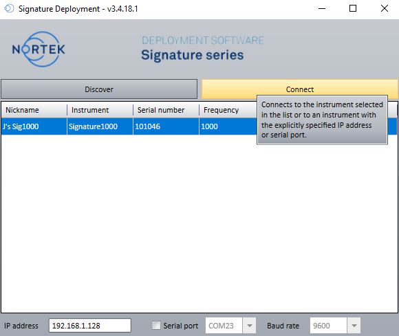
Figure 5: Connect to Signature instrument.
- Navigate to Planning|New Deployment to configure the Signature settings.
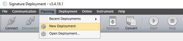
Figure 6: Deployment Settings.
- Run through the (5) configuration steps of the Deployment Wizard to configure the sensor for the desired conditions.
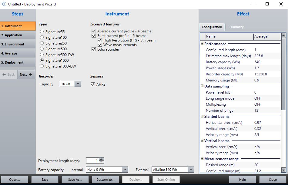
Figure 7: Deployment Wizard 1- Select the Signature instrument type.

Figure 8: Deployment Wizard 2- Select the Single Average Plan.
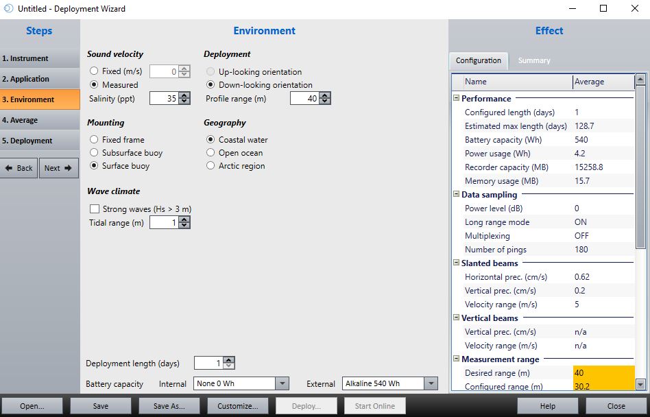
Figure 9: Deployment Wizard 3- Select the appropriate deployment and mounting settings.
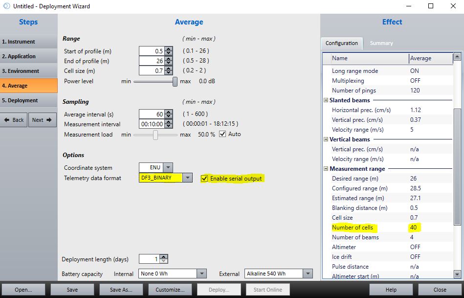
Figure 10: Deployment Wizard 4- enable serial output of the instrument telemetry file.
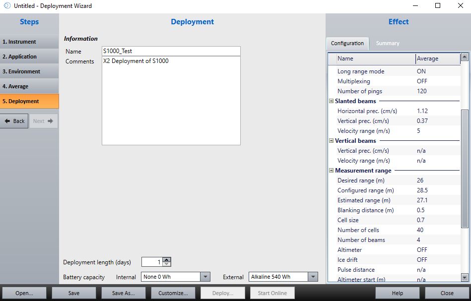
Figure 11: Deployment Wizard 5- name/save deployment configuration file and apply to Signature instrument.
- Save the configuration template, as desired, then click Deploy….
- A menu will appear with a summary of the configuration settings. Make sure the baud rate is set to 9600 and select Deploy a second time.
- Accept the prompt that no batteries are installed. The X2 logger will supply full external cable power to the Signature instrument during deployment.
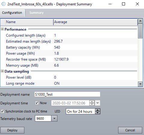
Figure 12: Deploy settings review.

Figure 13: Deployment settings are being applied.
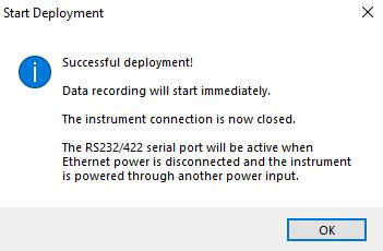
Figure 14: Successful Deployment.
Access Instrument Terminal
Certain configuration settings required to interface the Signature with the X2 may not be properly translated through the deployment file. Double-check the telemetry and cell configuration deployment settings through the Signature instrument terminal and make changes where required.
- Navigate to Communication|Connect to instrument in the Signature Deployment software and acknowledge the break to remove the sensor from its deployment.
- Go to Communication|Terminal Window
Confirm Telemetry File Settings
- Send the gettmavg command and check the instrument response to confirm the current telemetry file settings.
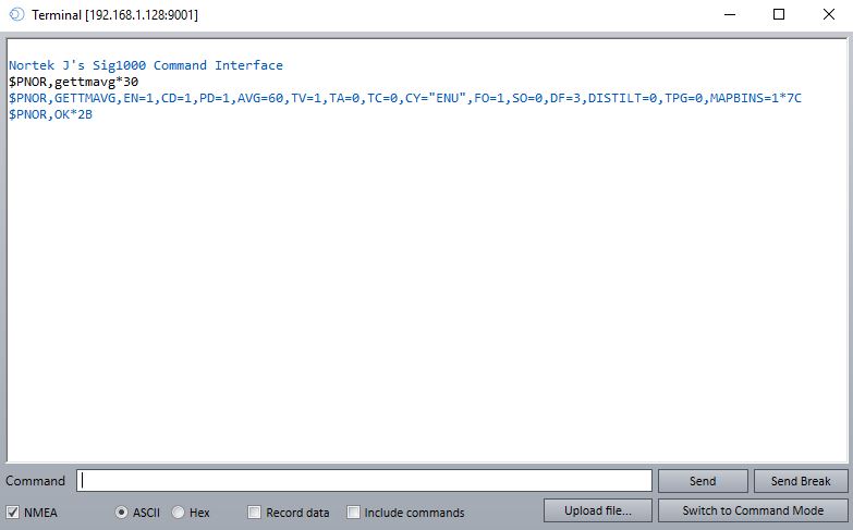
Figure 15: Instrument response to gettmavg command.
- Verify the telemetry settings returned match those values below.
- EN=1, indicates data output is enabled.
- TV=1, indicating velocity values for each deployment cell are enabled.
- TA=0, indicating amplitude values for each deployment cell are turned off.
- TC=0, indicating correlation values for each deployment cell are turned off.
- FO=1, indicates the file output is enabled.
- SO=0, indicates that serial output is disabled.
- DF=3, indicates that binary data output is enabled.
- If any portion of the telemetry file configuration requires a change, send the settmavg command followed by the parameter indicator and new status.
-
- For example, to set TA=1, the command settmavg,TA=1 would be sent.
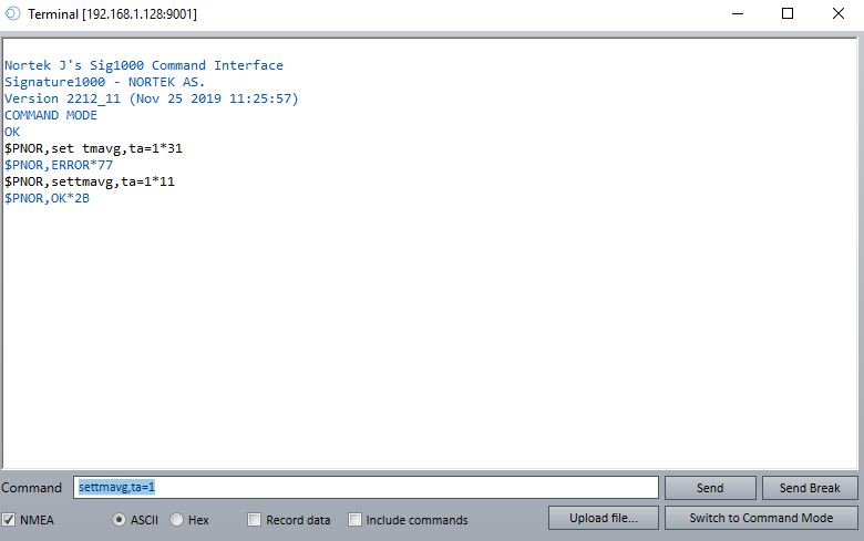

Figure 16: Setting the TA value equal to 1.
- For example, to set TA=1, the command settmavg,TA=1 would be sent.
-
- Note that multiple command changes can be sent in a single line provided each value is separated by a comma and no space.
-
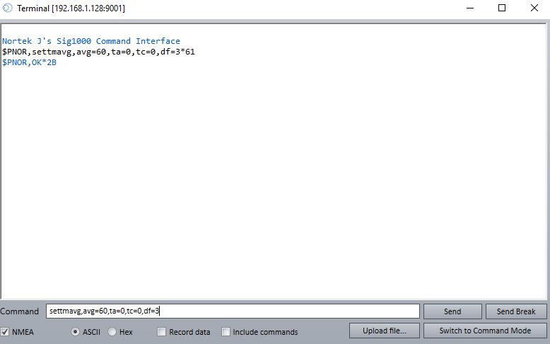
Figure 17: Example showing the average interval, TA, TC, and DF values being changed simultaneously.
Confirm Cell Measurement Settings
- Send the getavg command and check the instrument response to confirm the current cell measurement settings.
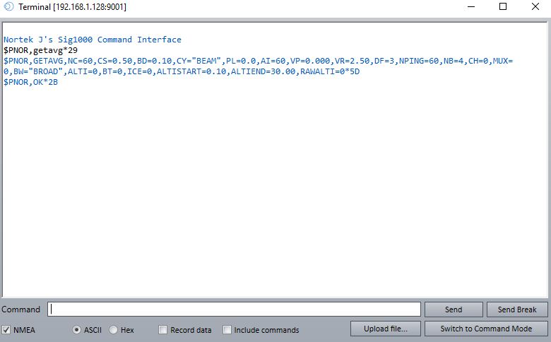
Figure 18: Instrument response to the ‘getavg’ command indicating the number and structure of measurement cells.
- Verify that the settings, particularly the ones below, align with the desired values configured from the deployment template.
- NC=x, indicates the # measurement cells the Signature instrument will monitor.
- NB=x, indicates the #measurement beams used by the instrument to monitor each cell.
- CS=x, indicates the length (in meters) of each measurement cell.
- AI=x, indicates the averaging interval for each reading (in seconds).
- ALTISTART=x, indicates the distance (relative to the sensor head) at which the 1st measurement cell begins.
- ALTIEND=x, indicates the distance (relative to the sensor head) at which the final measurement cell ends.
- Note that the X2 can support a maximum of 160 parameters from the Signature.
- The number of active parameters can be determined using the formula (NC*NB*(TA+TC+TV))<160
- NC represents the #cells, returned by the getavg command.
- NB displays the #measurement beams used, returned by the getavg command.
- TA is the cell amplitude flag (0-disabled, 1-enabled) returned from the gettmavg command.
- TC is the cell correlation flag returned from the gettmavg command.
- TV is the cell velocity flag returned from the gettmavg command.
- For example, a deployment with the following settings would have the maximum number of allowed parameters
- NC=40
- NB=4
- TA=0
- TC=0
- TV=1
- Calculation- (40 cells*4 beams*(0+0+1 velocity flag))=160 parameters
- The number of active parameters can be determined using the formula (NC*NB*(TA+TC+TV))<160
Save Configuration Changes and Redeploy
Once the deployment settings are verified to be correct, and the maximum number of Signature parameters for the X2 is not exceeded, save all settings.
- Send save,all command in the terminal.
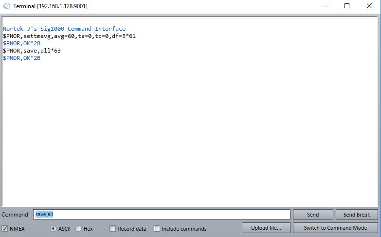
Figure 19: Save any settings changes that are made before disconnecting from the terminal.
- Send the DEPLOY command to put the instrument into Deployment mode.
- Refer to section 5.22 DEPLOY in the Nortek Signature Integration Guide for information on the key difference between the START and DEPLOY command.
- Close out of the terminal and the Signature Deployment software and disconnect the instrument from the AC power adapter and Ethernet cable.
- Connect the Signature to the X2 through a serial cable and power up the logger to begin sensor detection/data collection.
Applicable Systems
Water current measurements from Nortek ADCPs are useful in coastal and ocean-based environmental monitoring applications.