
S::CAN UV-Vis Spectrophotometer X2 Integration Guide
The S::CAN UV-VIS Spectrophotometer is a submersible UV-Vis spectrophotometer that analyzes spectral data to provide measurements for the following: nitrate (NO3–), nitrite (NO2–), chemical oxygen demand (COD), biochemical oxygen demand (BOD), total suspended solids (TSS), dissolved hydrogen sulfide (H2S), and many more. The sensor is compatible with the X2 data logger via the Modbus-RTU communication protocol and the RS-485 sensor interface.
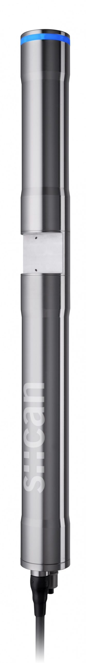
Figure 1: S::CAN SpectroLyser UV-Vis Monitor.
Sensor Terminal Connections
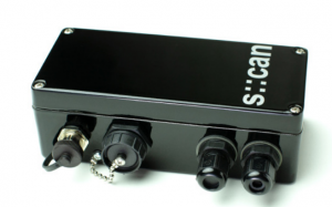
Figure 2: S::CAN con::nect junction box.
The con::nect junction box is utilized with the S::CAN UV-Vis Spectrophotometer to ensure power supply and sensor communication with the X2 data logger. Information regarding the wiring connections may be found in the table and images below:
| Cable Connection | Wire Color | Terminal Connection | Signal |
| NexSens Sensor Cable (Sensor Power: X2 Connection- P1) |
Red | + DC in | Sensor Power |
| Black | – DC in | Sensor Ground | |
| Green* | + DATA | 485A | |
| Blue* | – DATA | 485B | |
| NexSens Wiper Power Cable (Wiper Control: X2 Connection- P2) |
Red | NC (Top) | Wiper Control |
| Black | – 12V Out | Wiper Ground | |
| S::CAN Wiper Cable | Red | + 12V Out | Wiper Power |
| Black | – 12V Out | Wiper Ground | |
| Pink | NC (Top) | Wiper Control |
*150 ohm resistor jumped between 485 signals

*Note: The third and left-most sensor gasket is custom with NexSens integration.
Software Communication
Communication to the Io::Tool software will require an external power source (12VDC) via the UW8-Flx cable connection to the NexSens sensor cable on the S::CAN sensor.
- Remove the NexSens Sensor Cable from the P1 port on the X2.
- Plug the NexSens Sensor Cable into the receptacle on the UW8R-FLx external power cable.
- Connect a LAN ethernet cable between the ethernet ports on the con::nect junction box and a PC.
- Attach the flying leads of the UW8R-FLx to a 12VDC power source to power the S::CAN sensor.

Figure 4: Communication with Io::Tool software using ethernet connection and external power connected between the NexSens Sensor Cable on the S::CAN and a UW8-FLx cable to the power source.
- Open Network Connection to modify the Properties of your Ethernet connection.
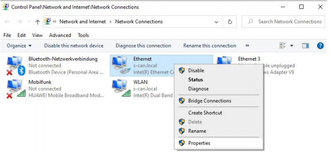
Figure 5: Adjust ethernet properties for S::CAN connection.
- Select Internet Protocol Version 4 and push the button Properties.
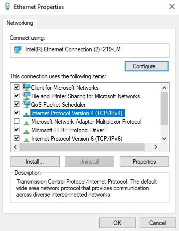
Figure 6: Internet Protocol Version 4
- Click Use the following IP address and enter the necessary IP address from the table below, based on the method of connection.
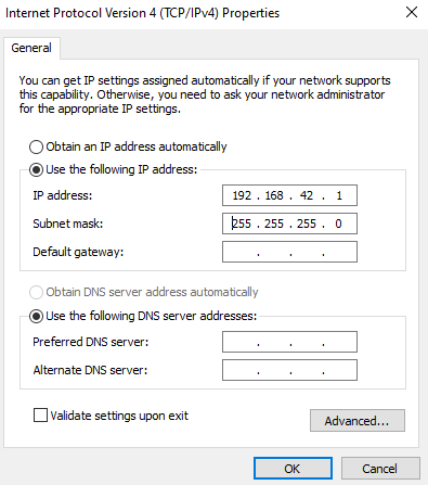
Figure 7: Internet Protocol Version 4 Properties
| Connection Method | IP address of spectrometer* | Remark |
| via WLAN | 192.168.43.1 | default address; password = spectrolyser |
| via Bluetooth | 192.168.44.1 | default address |
| via LAN | to be checked on DHCP Server | DHCP active on spectrometer probe per default |
| via LAN | 192.168.42.10 (Fixed static IP) | fall back (static) if network without DHCP Server (e.g. when connecting directly with notebook) |
*Follow page 11 of the con::nect manual to change the network settings on the spectrometer probe.
- Enter the IP address of the spectrometer probe into a web browser to start the Io::Tool.
S::CAN SpectroLyser Internal Setting Requirements
The following sensor settings are required for communication with the X2 data logger. These settings are default and should not be changed within the software; however, if the S::CAN sensor Modbus address (default = 4) interferes with any other Modbus sensor, this address must be changed before the sensor is detected by the X2.
- Baud Rate: 38400
- Parity: Odd
- Stop Bits: 1
- Default Address: 4
X2 Connection
Based on the X2 sensor script, the NexSens sensor cable must be plugged into port 1 (P1) on the X2 data logger and the NexSens wiper cable must be plugged into port 2 (P2). Follow the schematic below for proper connection to the X2 data logger. Ensure that this configuration is correct during sensor detection.
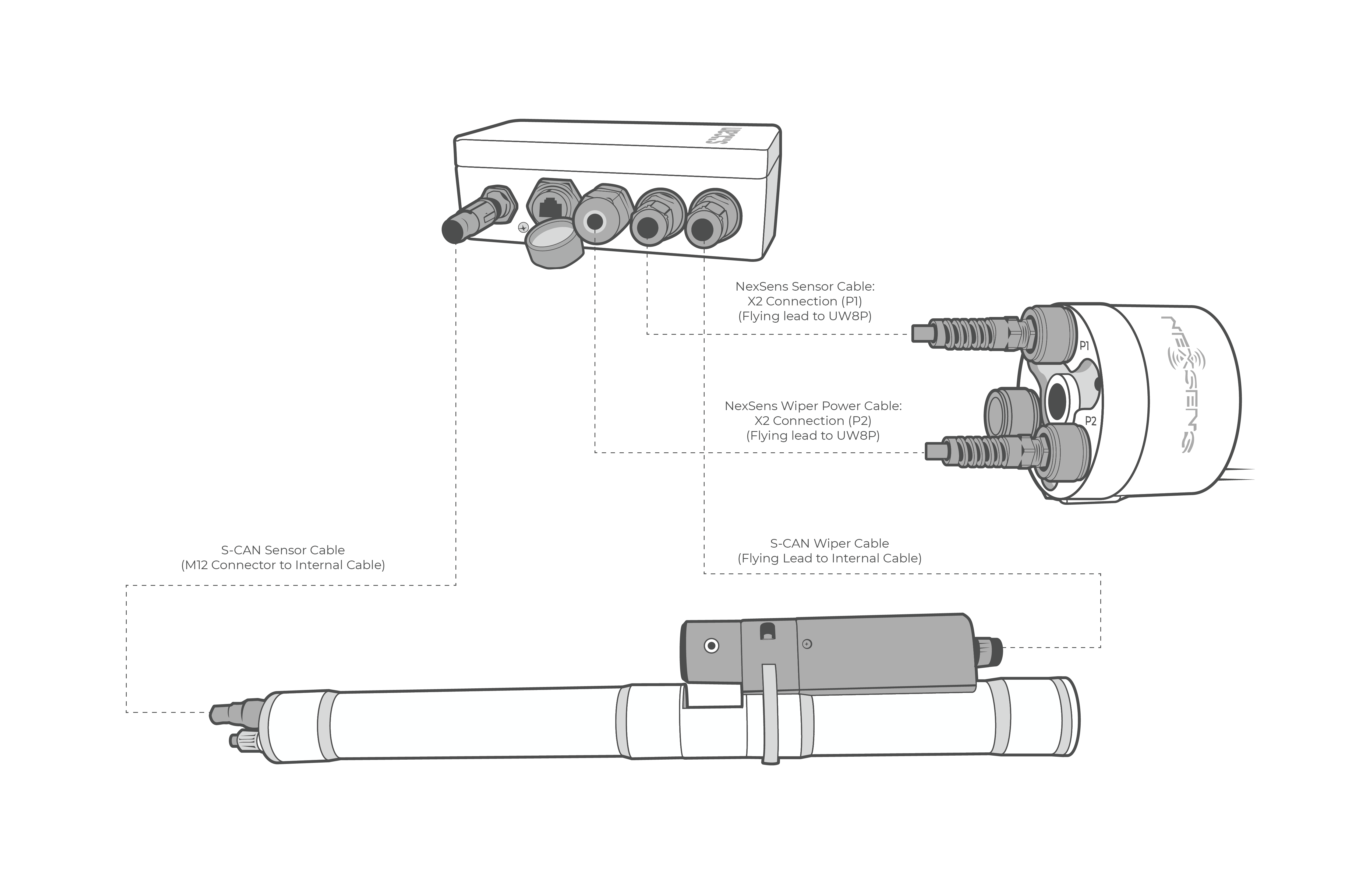
Figure 8: S-CAN X2 Connection Schematic. S::CAN sensor (NexSens Sensor Cable) must be plugged into P1 on the X2. S::CAN wiper cable must be plugged into P2 on the X2.
Applicable Systems
UV-Vis nutrient measurements from the S::CAN sensor are useful in various environmental monitoring applications.
- HABs Detection Systems
- Inland Lake Monitoring Systems
- Large Lake Monitoring Systems
- Nutrient Monitoring Systems