
NexSens T-Node FR Temperature Sensor User Guide
The NexSens T-Node FR Thermistor String provides high-accuracy temperature data at each node location in the water column. The sensor and cable assemblies are designed for temperature profiling up to 200 meters deep.
1. Install software and set up the computer
- Download and install NexSens CONNECT software on a field or lab computer.
- Plug the UW-USB-485R-DC cable adapter into the computer.
- Ensure the computer has access to the internet so the USB VCP drivers install automatically.
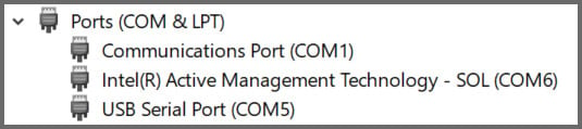
- Open Windows Device Manager and note the COM port for the USB Serial Port.
- If the device does not install properly, contact your IT administrator to manually install drivers from the VCP Driver download.
2. Sensor Setup
- Plug the UW-USB-485R-DC cable adapter into one of the nodes.
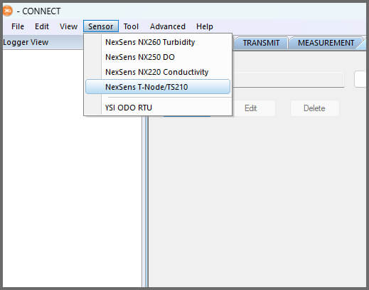
- Click Sensor in the top left and select the NexSens T-Node/TS210 from the dropdown.
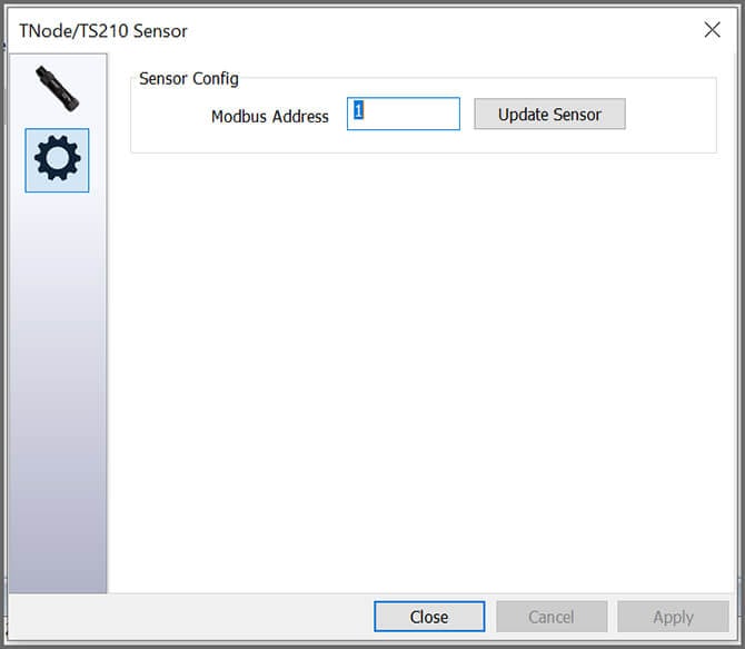
- Select the COM port and enter the Modbus Address (251 if not known) and click Connect.
- Ensure the T-Node is collecting temperature readings.
- Confirm the Modbus Address and update it if needed in the Settings by clicking the gear icon.
- Repeat for each T-Node and set the Modbus Addresses in numerical order, ensuring they do not overlap with other Modbus sensors on the system.
3. Data Logger Connection
The T-Node FR interfaces to data loggers with RS-485 Modbus protocol or SDI-12 with an optional adapter.
Connecting to NexSens X-Series Data Loggers
- Assemble the thermistor string starting with the lowest address.
- Plug the top node into one of the open sensor ports on the logger using the supplied cable. Be sure to note the port number.
- Plug the X3 into the USB port of the computer and power it on with the AC power cable.
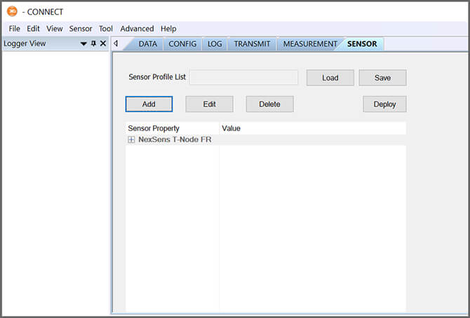
- Select the Sensor tab in CONNECT.
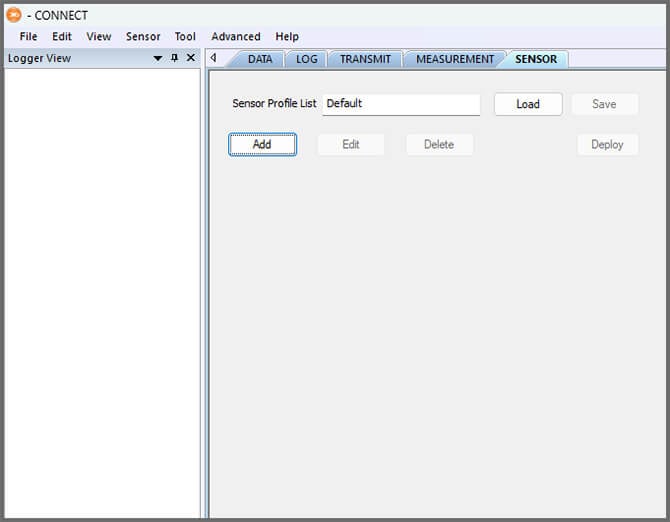
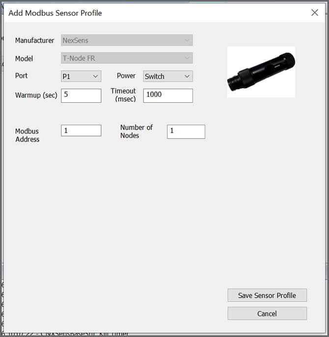
- Click Add and select NexSens from the Manufacturer dropdown. Then select the appropriate model.
- Enter the port number and select either Continuous or Switch in the Power dropdown.
- Switch is recommended for the T-Node FR.
- Enter the starting node’s Modbus address and the total number of nodes.
- The Modbus address will be automatically assigned for the rest of the nodes. For example, entering Modbus Address 1 and Number of Nodes 5 results in Modbus Addresses 1, 2, 3, 4, 5.
- Select Save Sensor Profile.
- Complete the setup for all other sensors, and then click Deploy.
- Confirm that data is being transferred to WQData LIVE.
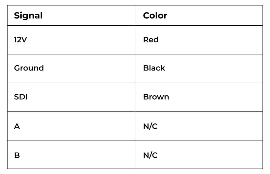
Connecting to SDI-12 Data Loggers
Use the optional RS485-SDI12 adaptor to convert the sensor to SDI-12. Connect as shown and follow standard SDI-12 protocol.
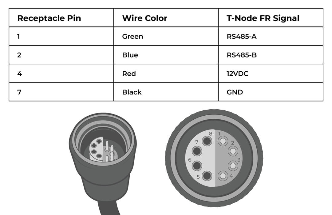
Connecting to Other RS-485 Modbus Data Loggers
For other RS-485 Modbus data loggers, use the wiring pinout and Modbus commands found in Appendix A.
4. Mounting
Deployment setups will vary based on the platform, application, and site location. For general buoy mounting instructions, see below.
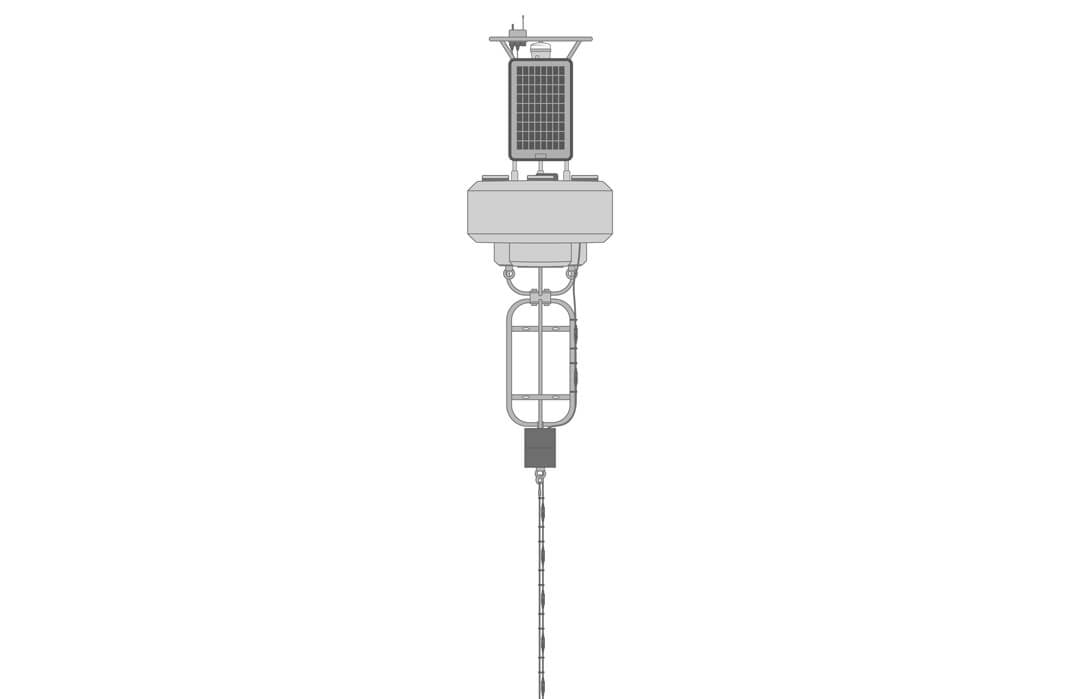
Buoy-Based Deployments
First, follow the appropriate User Guide in the Knowledge Base for buoy assembly. Then use the Thermistor String Mooring Clamp Kit to secure the string to a sensor line.
- Slide the included large o-ring onto the T-NODE cable and the smaller o-ring on the mooring line above and below each node.
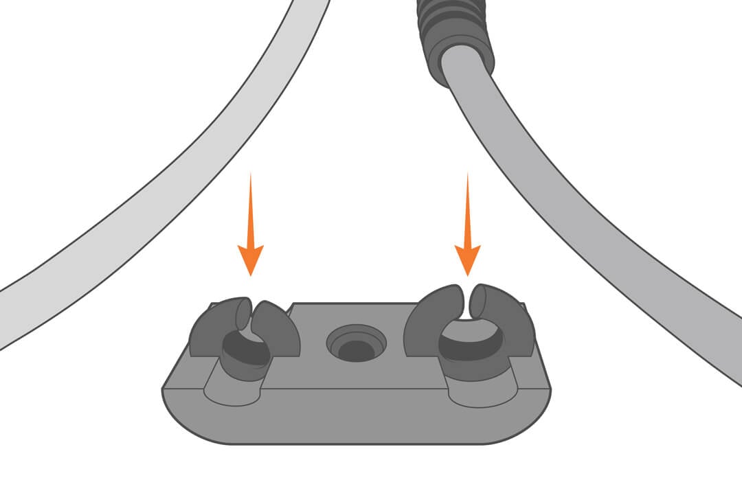

- Close the clamp, ensuring to pull the lines taught before securing.
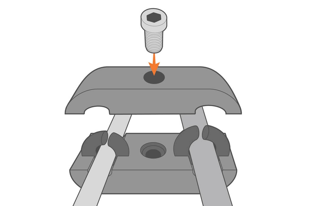
- Repeat as needed.
- Route the assembled string through the pass-through port on the buoy.
- Secure the string to the buoy’s instrument cage.
5. Inspection and Maintenance
Periodically inspect and clean temperature strings, including cable and sensors. This is best accomplished with soap and a soft-bristled brush without disassembly.
WARNING: Never allow moisture to enter any of the UW connectors during cleaning.
Storage
T-Nodes should be stored in a cool, dry place.
6. Troubleshooting
| Problem | Potential Causes | Solutions |
|---|---|---|
| Temperature data not recording. | Leakage into a connector | Check each underwater connection for flooding. Clean and/or replace seals. Relubricate the seals with a thin film of o-ring grease. |
| String disconnected (or severed) | Check the physical setup and condition of the temp string. | |
| No power | Use a DVM to verify the input power is registering 5-24VDC |
7. NexSens Warranty
View the NexSens Warranty.
8. NexSens Service Request
To return equipment for evaluation and repair, visit this page for more information.
Appendix A
RS-485 Modbus wiring pinout and commands.
| Communication Attributes | |
| Universal Modbus Address: | 251 |
| Baud Rate: | 19200 |
| Parity: | None |
| Data Bit: | 8 |
| Stop Bit: | 1 |
| Register Address (Hex) | # of Registers | Name | Access | Limits or Range | Units | Data | Function Code | Comments | Test Request | Test Response | ||
|---|---|---|---|---|---|---|---|---|---|---|---|---|
| 4096 (0x1000) | 1 | Get/Set Modbus Device address | Read/Write | 1-247 | — | 16-bit integer | 0x04, 0x10 | Use Get command with universal address 251 (0xFB) |
FB,04,10,00,00,01,21,50 (Get current modbus address) |
FB,04,02,00,07,20,E6 (Current modbus address is 7) |
01,10,10,00,00,01,02,00,05,77,92 (Change Modbus address from 1 to 5) |
01,10,10,00,00,01,05,09 |
| 4105 (0x1009) | 2 | Get Software version | Read Only | — | — | 32-bit unsigned integer (big endian) | 0x04 | Version number scale 100 (i.e. 103 = v1.03) | ||||
| T-Node FR Sensor | ||||||||||||
|
6 (0x0006) |
2 |
Read temperature |
Read Only |
— | °C |
Floating point (Big endian) |
0x04 |
Register 6: Most significant 16-bit of float value Register 7: Least significant 16-bit of float value |
||||
|
4103 (0x1007) |
2 |
Get/Set device NID |
Read/Write |
— | °C |
32-bit unsigned integer (big endian) |
0x04, 0x10 | |||||