Use a Terminal Emulator to Configure a Nortek Sensor
If unable to access the Nortek software, configuration settings required to interface the Signature with the X2 may be adjusted through a third party terminal emulator such as TeraTerm. Double-check the telemetry and cell configuration deployment settings through the third party terminal emulator and make changes where required.
- Connect the 8-pin MCIL plug of the Nortek Signature Series serial communication cable to the receptacle labeled Serial at the bottom of the instrument and connect the DB9 serial connector to a PC.
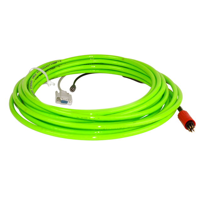
Figure 1: Nortek Signature Series Serial Communication Cable
- Open the third party terminal emulator software, and ensure to input the correct Serial Port Setup.
- COM Port: Use PC device manager to choose the correct COM port connected to the instrument.
- Baud Rate: Default is 9600; however, the baud rate may have changed on the user device.
- Data: 8 bit
- Parity: none
- Stop bits: 1 bit
- Flow control: none
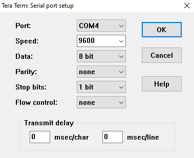
Figure 2: Serial port setup
- Use an AC power adapter to provide 24V power to the barrel connector on the communication cable.
- The following message should appear within the terminal emulator.
Figure 3: Bootloader message
Set Telemetry File Settings
Note: Depending on the third party terminal emulator, the user inserted commands may not display in the interface. An error message will appear after the user clicks enter if the inserted command is entered incorrectly. If the command is entered correctly, output should display in the emulator similar to the images at each step in the process below.
- Send the gettmavg command, click enter, and check the instrument response to confirm the current telemetry file settings.
| Argument | EN | CD | PD | AVG | TV | TA | TC | CY | FO | SO | DF | DISTILT | TPG | MAPBINS |
| Example Output Below | 0 | 1 | 1 | 0 | 1 | 1 | 1 | “ENU” | 1 | 0 | 100 | 0 | 0 | 1 |
Figure 4: Example gettmavg output: Matches output table above
- Verify the telemetry settings returned match those values below. Orange settings must have the listed values. Those in Green can vary depending on the user’s desired measurement setup.
- EN=1, indicates data output is enabled.
- TV=1, indicating velocity values for each deployment cell are enabled.
- TA=0, indicating amplitude values for each deployment cell are turned off.
- TC=0, indicating correlation values for each deployment cell are turned off.
- FO=1, indicates the file output is enabled.
- SO=0, indicates that serial output is disabled.
- DF=3, indicates that binary data output is enabled.
- If any portion of the telemetry file configuration requires a change, send the settmavg command followed by the parameter indicator and new status.
- For example, to set EN=1, the command settmavg,EN=1 would be sent.
Figure 5: Set Enable Averaging Mode Telemetry by inputting: settmavg,EN=1
- Note that multiple command changes can be sent in a single line provided each value is separated by a comma and no space.
- Example below: Sent the following command to match the telemetry settings in step 2 of Set Telemetry File Settings.
- settmavg,TA=0,TC=0,DF=3
- Example below: Sent the following command to match the telemetry settings in step 2 of Set Telemetry File Settings.
- Note that multiple command changes can be sent in a single line provided each value is separated by a comma and no space.
Figure 6: Updated getmmavg after sending the following command: settmavg,TA=0,TC=0,DF=3
Set Cell Measurement Settings
- Send the getavg command and check the instrument response to confirm the current cell measurement settings.
| Argument | NC | CS | BD | CY | PL | AI | VP | VR | DF | NPING | NB | CH | MUX | BW | ALTI | BT | ICE | ALTISTART | ALTIEND | RAWALTI |
| Example Output Below | 60 | 0.50 | 0.10 | “BEAM” | 0.0 | 60 | 0.000 | 2.50 | 3 | 60 | 4 | 0 | 0 | “BROAD” | 0 | 0 | 0 | 0.10 | 30.00 | 0 |
Figure 7: Example getavg output: Matches table above
- Verify that the settings, particularly the ones below, align with the desired values configured from the deployment template.
- NC=x, indicates the # measurement cells the Signature instrument will monitor.
- NB=x, indicates the #measurement beams used by the instrument to monitor each cell.
- CS=x, indicates the length (in meters) of each measurement cell.
- AI=x, indicates the averaging interval for each reading (in seconds).
- ALTISTART=x, indicates the distance (relative to the sensor head) at which the 1st measurement cell begins.
- ALTIEND=x, indicates the distance (relative to the sensor head) at which the final measurement cell ends.
- If any portion of the measurement settings require a change, send the setavg command followed by the parameter indicator and new status.
- For example, to set NC=4, the command setavg,NC=4 would be sent.
Figure 8: Set Number of Cells to 4 by inputting: setavg,NC=4
- Note that multiple command changes can be sent in a single line provided each value is separated by a comma and no space.
- Example below: Sent the following command to change the Cell Size (CS) to 4m, Blanking Distance (BD) to 3.5m, and Altimeter end of measurement distance (ALTIEND) to 25.00m.
- setavg,CS=4,BD=3.5,ALTIEND=25.00
- Example below: Sent the following command to change the Cell Size (CS) to 4m, Blanking Distance (BD) to 3.5m, and Altimeter end of measurement distance (ALTIEND) to 25.00m.
- Note that multiple command changes can be sent in a single line provided each value is separated by a comma and no space.
Figure 9: Updated getavg output after sending the following command: setavg,CS=4,BD=3.5,ALTIEND=25.00
- Note that the X2 can support a maximum of 160 parameters from the Signature.
- The number of active parameters can be determined using the formula (NC*NB*(TA+TC+TV))<160
- NC represents the #cells, returned by the getavg command.
- NB displays the #measurement beams used, returned by the getavg command.
- TA is the cell amplitude flag (0-disabled, 1-enabled) returned from the gettmavg command.
- TC is the cell correlation flag returned from the gettmavg command.
- TV is the cell velocity flag returned from the gettmavg command.
- For example, a deployment with the following settings would have the maximum number of allowed parameters
- NC=40
- NB=4
- TA=0
- TC=0
- TV=1
- Calculation- (40 cells*4 beams*(0+0+1 velocity flag))=160 parameters
- The number of active parameters can be determined using the formula (NC*NB*(TA+TC+TV))<160
Save Configuration Changes and Deploy
Once the deployment settings are verified to be correct, and the maximum number of Signature parameters for the X2 is not exceeded, save all settings.
- Set a new file name for the deployment by entering SETPLAN,FN=”[filename].ad2cp”.
- Brackets around the file name are not required. For each new deployment, a different file name will need to be entered.
- Send the save,all command in the terminal.
- An “OK” message should be received.
- Send the DEPLOY command to put the instrument into Deployment mode.
- An “OK” message should be received.
- Refer to section 5.22 DEPLOY in the Nortek Signature Integration Guide for information on the key difference between the START and DEPLOY command.
- Close out of the terminal and the Signature Deployment software and disconnect the instrument from the AC power adapter and serial cable.
- Connect the Signature to the X2 through a serial cable and power up the logger to begin sensor detection/data collection.
- Ensure to enable script 3015- Nortek Signature ADCP by following the article below:
Returning to Command Mode
If further changes are necessary in the future, the user will need to return the instrument to Command Mode to make changes.
- In the terminal, input the following break command K1W%!Q and click enter. Wait for one minute until beginning the next step.
- Hit enter on your keyboard. The terminal should output CONFIRM OK.
- Once this occurs, type MC into the terminal and click enter to begin Command Mode.
- The bootloader message should appear.
Figure 10: Bootloader message
- Follow the previous sections of this guide to make changes to the internal settings, save the settings, and then put the sensor back into deployment mode.