NexSens iSIC and SDL500 data loggers can communicate using interfaces such as SDI-12, Modbus RS-485 and RS-232. This process shows how to switch from SDI-12 or Modbus to RS-485 communication in order to allow connection to a PC.
1a. Open iChart without a current project.
2a. From the main menu select Advanced | Terminal…
3a. Select the correct PC COM Port and the appropriate Connection from the drop down menu. Do not check the “Use iSIC” box.
4a. Cycle power to the data logger and wait for the boot record to appear to indicate device communication. The “%SDI12″ or “%MODBUS” indicates that the device is in SDI-12 or Modbus mode respectively. In this mode, the iSIC will only accept SDI-12 or Modbus commands respectively.
To cycle power from an iSIC logger, remove the two black fuses on the lefthand side of the mounting plate. Replace the “Battery” fuse to reapply power.
To cycle power from an SDL500 logger, remove any D-cell batteries installed inside the battery ports, and disconnect the USB cable at the end connected to the SDL500 top port. Reconnect the cable to the top port to reapply power.
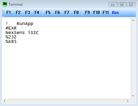
Figure 1: Terminal window, note last line ending with %485
5a. Cycle power to the logger again. As soon as “NexSens” appears on the terminal screen, press <ESC>485. “%485″ will immediately be displayed in place of “%SDI12″ or “%MODBUS”.
6a. From the Main Menu select File | Close.
7a. From the Main Menu select Advanced | iSIC | iSIC.
8a. Select the correct PC COM Port, iSIC Address and the appropriate Connection from the drop down menu. Click Connect.
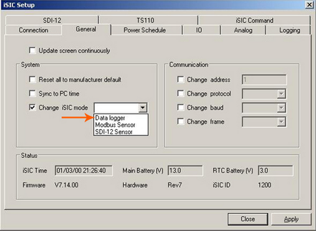
Figure 2: Change iSIC mode
9a. Switch to the General tab. After a few seconds, the Status group box should be populated.
10a. Check the “Change iSIC mode” box and select Data logger from the drop down menu. Click Apply.
11a. Uncheck the “Change iSIC mode” box and click Close. At this point, the logger is communicating through the RS-485 cable that is connecting to it directly and is in data logger mode. Programming or other diagnostics may be performed, but cycling power will cause the logger to communicate through RS-232, its default, and it will be necessary to use the Terminal again so that the logger can communicate through an RS-485 cable.
To switch back to SDI-12 or Modbus RS-485 mode:
1b. From the Main Menu select Advanced | iSIC | iSIC.
2b. Select the correct PC COM Port, iSIC Address and the appropriate Connection from the drop down menu. Click Connect.
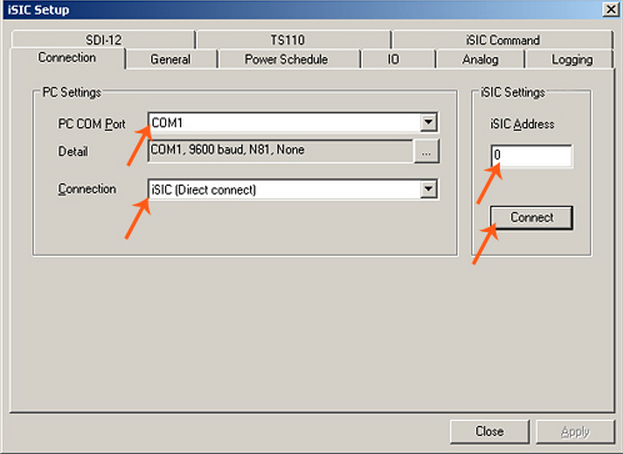
Figure 3: iSIC Setup window
3b. Switch to the General tab. After a few seconds, the Status group box should be populated.
4b. Check the “Change iSIC mode” box and select SDI-12 Sensor or Modbus Sensor from the drop down menu depending on what is required. Click Apply.
The SDL is now configured to operate as an SDI-12 or Modbus sensor. This can be verified by repeating Steps 2a-4a.
REV: 13G29