NexSens iSIC and SDL500 data loggers can be setup to send data to a Modbus slave device after logging data to the internal flash memory. This is a “hybrid” data logger/Modbus device mode. The iSIC or SDL500 may be set in this mode by sending a command through the control menu:
1. Enable the iSIC Command tab in the iSIC Setup menu:
http://www.nexsens.com/knowledge-base/software/ichart/enable-isic-command-tab.htm
2. Go to Advanced | iSIC | iSIC to access the iSIC Setup menu.
3. Enter the appropriate communication parameters (PC COM port, Connection type, iSIC/SDL Address) and click Connect.
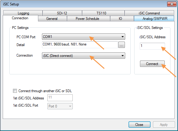
Figure 1: iSIC Setup Menu
4. Click the General tab. Confirm that the connection was successful by viewing the information in the Status group box. If any fields display “???”, go back to Step 3 and attempt to reconnect.
5. Confirm that the iSIC or SDL500 is set to Data logger mode. If it is not, check the box next to Change iSIC mode and select Data logger from the drop-down list. Click Apply to submit the change.
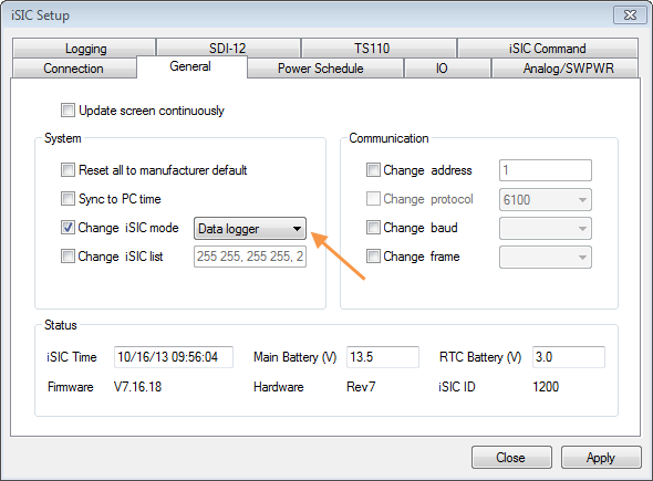
Figure 2: iSIC Setup Menu General Tab
6. Click the iSIC Command tab. Select GSET_MODBUSOUTPUTCFG from the Command drop-down list.
7. Enter the appropriate argument to configure the iSIC or SDL500 and click Send. Arguments are entered in the format [0] [1] [2] [3] [4..5] [6] [7] [8] [9] [10..11] [12]. See the Appendix at the end of this article for an explanation of the argument fields 0-12.
Two examples are shown below:
Example 1: Query current Modbus settings
Command: GSET_MODBUSOUTPUTCFG
Argument: none (empty)
Response
Send: 21 01 64 06 ad 00 e8
Receive: 21 64 01 07 06 0e 00 00 00 01 00 00 02 06 03 00 32 00 02 00 40
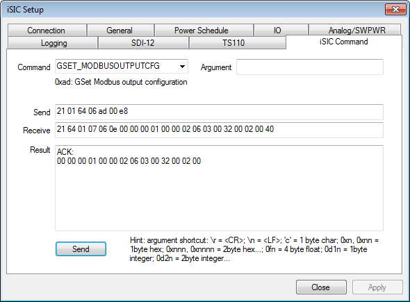
Figure 3: Query Current Modbus Settings
Example 2: Set Modbus output configuration (to Modbus RTU, address 1, starting register 0000, 16-bit unsigned data type, RS485 port, 9600 baud)
Command: GSET_MODBUSOUTPUTCFG
Argument: 1 0 0 1 0x0000 0 6 3 0 0x0064 3 0
Response
Send: 21 01 64 0f ad 0e 01 00 00 01 00 00 00 06 03 00 64 00 03 00 5f
01 – Enable Modbus output
00 – Modbus RTU
00 – Do NOT write timestamp to Modbus slave device
01 – Modbus address 1
00 00 – Starting Modbus register 0000
00 – Data type 16-bit unsigned
06 – Port RS485
03 – Baud 9600
00 – Frame 1 start bit, 8 data bit, 1 stop bit, no parity
64 00 – Timeout 100 = 1000ms = 1second
03 – Retries 3
00 – Do NOT skip bad data
Receive: 21 64 01 10 06 0e 01 00 00 01 00 00 00 06 03 00 64 00 04 00 04
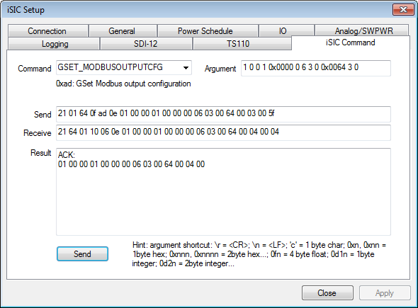
Figure 4: Set Modbus Output Configuration
Appendix – Argument Fields
[0] – Active flag
- 0: Set Modbus output OFF
- 1: Set Modbus output ON
[1] – Modbus type
- 0: RTU
- 1: ASCII
[2] – Output timestamp
- 0: do NOT output sample timestamp
- 1: Output sample timestamp (UNIX Epox) in the first 2 register
[3] – Modbus address
[4..5] – Starting Modbus register (little endian)
[6] – Data type
- 0: 16-bit unsigned
- 1: 32-bit unsigned (big endian)
- 2: 32-bit IEEE 754 float (big endian)
- 3: 32-bit unsigned (little endian)
- 4: 32-bit IEEE 754 float (little endian)
[7] – iSIC port (0 to 5 for RS232 port 0 to RS232 port 5; 6 for RS485)
- 0: RS-232 port 0 (MS8 connector)
- 1: RS-232 port 1 (Pins 5 and 6 [P1.Rx, P1.Tx] on iSIC Digital Terminal)
- 2: RS-232 port 2 (Pins 8 and 9 [P2.Rx, P2.Tx] on iSIC Digital Terminal)
- 3: RS-232 port 3 (Requires digital expansion)
- 4: RS-232 port 4 (Requires digital expansion)
- 5: RS-232 port 5 (Requires digital expansion)
- 6: RS-485 port (Pins 11 and 12 [P3.Rx, P3.Tx] on iSIC Digital Terminal)
[8] – Baud rate
- 0: 1200 baud
- 1: 2400 baud
- 2: 4800 baud
- 3: 9600 baud
- 4: 19200 baud
- 5: 38400 baud
- 6: 57600 baud
- 7: 115200 baud
[9] – Frame
- 0: N81 – 1 start bit, 8 data bit, 1 stop bit, no parity
- 1: E71 – 1 start bit, 7 data bit, 1 stop bit, even parity
- 2: E81 – 1 start bit, 8 data bit, 1 stop bit, even parity
- 3: O81 – 1 start bit, 8 data bit, 1 stop bit, odd parity
[10..11] – Timeout in 10ms (little endian), i.e. 1 = 10ms
[12] – Number of retries
[13] – Skip bad data flag
- 0: do NOT skip bad data – write bad data to Modbus slave device
- 1: skip bad data – do not write bad data to Modbus slave device
REV: 13K16