iChart includes advanced tools to view, diagnose and check sensor and data logger functionality. To access these tools, select Advanced | iSIC | iSIC from the iChart menu system. The iSIC Setup dialog box will open:
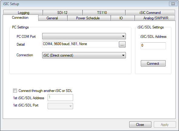
Figure 1: iSIC Setup window
On the first screen, select the COM port, connection method and address of the desired data logger. For example, if trying to connect to a 2100-iSIC with a modem connected to COM3, select 2100-iSIC from the connection drop down menu, and COM3 from the COM port menu. The address will typically be “1” unless connecting to a 4100-iSIC. When this information has been correctly entered, click the Connect button.
After clicking the connect button, the button text will switch to Disconnect after successfully connecting to the data logger. Next, click on any of the other tabs to access specific diagnostic information:
The General tab contains information such as firmware version, real time clock, log interval and other basic iSIC information.
The Power Schedule tab contains the power schedule for the iSIC. Unless battery conservation is necessary for the system to stay operational, it is usually not recommended to use this feature.
The Analog/SWPWR tab displays raw voltage readings on the analog channels of the iSIC and an option to turn Switch Power on or off.
The SDI-12 tab gives an interface to send SDI-12 commands directly to SDI-12 sensors connected to the data logger.
The TS110 tab gives an interface to communicate to a TS110 temperature string or T-Node temperature string and quickly view the temperature readings of each element in the string.
The Logging tab gives information on Log and Sample intervals and an option for checking Flash Memory status.
The IO tab allows for testing the Input/Output lines in iSIC data loggers.
The iSIC Command tab is an advanced tab used by NexSens Customer Support.
General Tab

Figure 2: General tab
The general tab allows users to see basic iSIC information such as the iSIC time, battery voltage, and firmware version. Most items can be updated by putting a check in the box next to them and, if needed, entering new information. Click Apply for the readings to take effect.
Sync to PC time: Check this box if the iSIC Time is not the same as the iChart computer’s clock.
Change address: Changes the iSIC address. This should only be done on 4100-iSICs. Note, no two 4100-iSICs should have the same address. As each iSIC ships with address 1, it is important to change the address when using more than one iSIC.
Change Protocol: Changes the iSIC protocol under which an iSIC is operating. Use this only under NexSens direction.
Reset all to manufacturer default: Sets the iSIC to its default settings. Use of this feature requires NexSens assistance and is usually never required.
Battery voltage required for iSIC operation will depend on the power settings set in the Power Schedule tab. This tab also shows recommended power settings for each type of iSIC or SDL500. For iSIC data loggers with SLA battery, the recommended low bat threshold is 11.2V and the high bat threshold is 12V. Recommended SDL thresholds are as follows:
- Cellular (SDL500C): 9.5V and 10.5 V
- Radio (SDL500R): 7.5V and 8.5V
- Buoy (SDL500C, SDL500R or SDL500I): 9.7V and 10.5V
The communication (cellular modem, satellite modem or radio) will turn off at the set low threshold. This setting allows power to be used for logging data. When the voltage goes back above the set high threshold, the communication will turn back on, and data collected during the lapse will then be pulled into iChart via auto-interrogation.
The RTC (Real Time Clock) Battery voltage should typically range from 2.7 to 3.3. When the battery voltage drops below these levels dramatically (approaching zero volts), the iSIC will not hold a time whenever the iSIC is powered down. This means that every time the iSIC battery is disconnected, the iSIC time will reset. The iSIC cannot log data when the time resets.
Note: An iSIC with a dead RTC battery will need to be returned to NexSens for a replacement.
Logging Tab
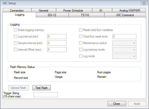
Figure 3: Logging tab
The Logging tab allows users to view the memory capacity, memory page structure, amount of memory used, data record size, and display an estimate of the amount of time left before the memory is full.
Erase logging memory: Usually does not need to be done unless old data isn’t supposed to be uploaded into a new iChart database. By default, the iSIC will store the last 150,000 readings. Additionally, if the iSIC is configured for “Stop” log memory mode, the memory must be erased after each upload to avoid memory filling up in the iSIC and preventing new data from being logged.
Upload Flash: If there are any problems with uploading the data, or it appears that the memory is corrupted, the entire flash memory of the data logger can be uploaded for analysis. The file can be uploaded in full, or only part of the flash can be uploaded. This feature is never required unless directed to do so by NexSens Customer Support.
REV: 13G10