Some analog sensors, such as a Turner Designs Cyclops-7 fluorometer, have different gain settings that allow the sensor to achieve high accuracy across a wide range of concentrations. When used with a mV-485 adapter, the gain setting is controlled within the adapter and can be changed using the process described below.
1. Establish a connection to the mV-485 adapter through iChart: www.nexsens.com/knowledge-base/nexsens-sensors/mv-485/connecting-mv-485-adapter.htm.
2. Once connected, navigate to the Modbus Command tab.
3. To read the current gain setting, select the Read gain command from the drop-down list and click Send. The Argument field can be left blank. The current setting will show in the Result box.
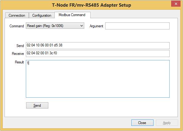
Figure 1: Read Current Gain Setting
4. To change the setting, select Write gain from the Command list and enter the desired setting in the Argument field. Gain settings are typically factors of 10 such as 1, 10 and 100. The available options vary by sensor. Consult the manufacturer’s sensor documentation for this information.
5. Click Send to set the value. The new value will be shown in the Result box.
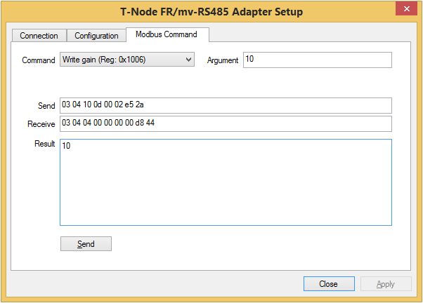
Figure 2: Change Gain Setting
6. When the gain setting is changed, the adapter configuration must also be updated to match the new gain setting. Click on the Configuration tab and review the values in the Point 1 and Point 2 fields. Using the manufacturer’s sensor documentation, identify the appropriate scaling factors for the current gain setting. Check the Edit box to edit the values, and click Apply to submit any changes.
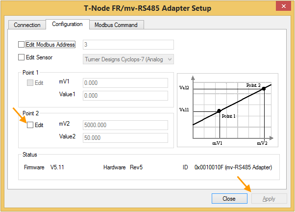
Figure 3: Update Configuration Settings
REV: 14G08